Introduction
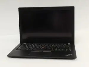
Follow this guide to safely remove and replace the motherboard in your Lenovo ThinkPad X280. You may need to replace the motherboard if your laptop experiences hardware failure, such as no power, random shutdowns, or unresponsive components. Ensure you have the required tools and a compatible replacement motherboard before starting. This process involves disconnecting delicate internal components, so handle all connections and parts with care to avoid damage.
-
-
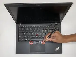
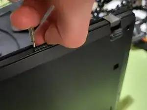
Using the flat end of the spudger, insert it at the top of the right click button.
-
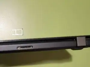
Pry it up to remove the button.
-
-
-
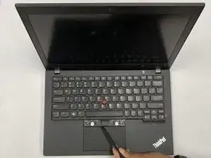
Using the black spudger tool, gently lift under the plastic where the screws were located.
-
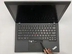
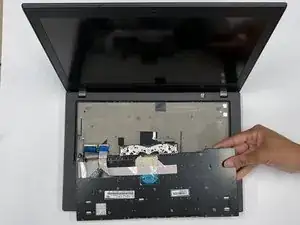
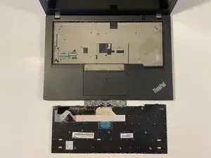
Slide the keyboard towards the screen of the LenovoThinkPad X280 and lift the front edge by hand.
-
-
-
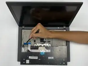
Gently pull the cables from the rectangular connection site to detach the keyboard.
-
Remove the keyboard.
-
-
-
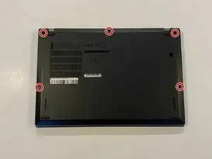
Use a Phillips #1 screwdriver to unscrew the five captive screws on the back panel until a small pop is heard.
-
-
-
Gently wedge an opening tool or spudger under the back panel, and loosen the clips around the perimeter until the back panel comes off.
-
Remove the back cover.
-
-
-
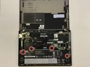
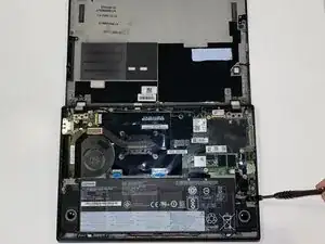
Using the Phillips #1 screwdriver, remove the four 5 mm screws that are holding the battery down.
-
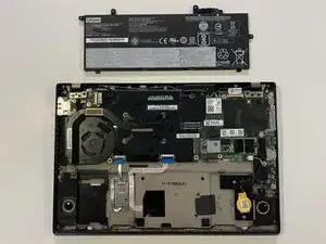
Remove the battery.
-
-
-
use a screwdriver or a spudger to flip up the two black ZIF locking flaps that secure the ribbon cables.
-
Disconnect the two ribbon cables.
-
-
-
Carefully use a spudger or a screwdriver to flip up the two locking flaps the metal retaining clips and disconnect the two ribbon cables from their sockets.
-
-
-
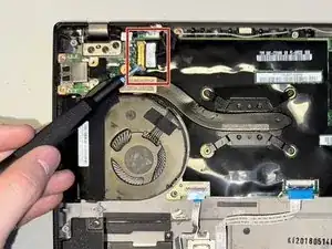
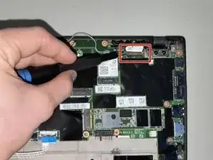
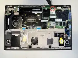
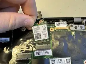
Use a Phillips #1 screwdriver to remove the single 3 mm screw securing the Wi-Fi card.
-
Gently pull the Wi-Fi card out of its slot at an angle to prevent damage to the connectors.
-
-
-
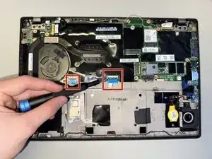
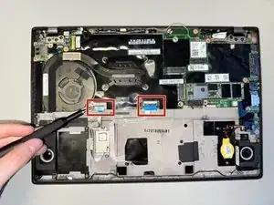
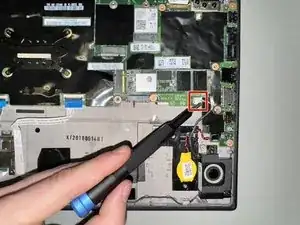
Use nails or a spudger to gently disconnect the first two plastic connectors from the motherboard by carefully pulling each one straight out of its socket.
-
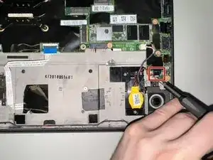
Disconnect the power button (third picture) with a spudger by nudging it, alternating on right and left sides, until it can be pulled out.
-
-
-
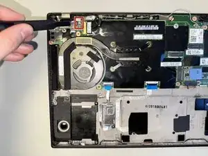
Remove the four 5.4 mm screws securing both the metal and plastic covers using a Phillips #1 screwdriver.
-
Gently lift and remove the covers to expose the internal components.
-
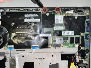
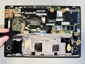
Unscrew the remaining fourteen 3.4 mm screws using a Phillips #1 screwdriver.
-
-
-
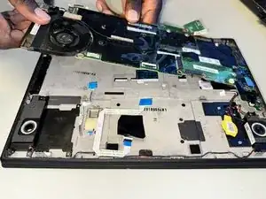
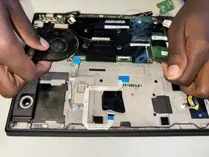
Carefully lift the motherboard by gently bending it to release it from its secured position.
-
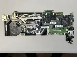
Once it is loose, pull it out and away from the case, ensuring all connectors and screws are detached to avoid damage.
-


To reassemble your device, follow the above steps in reverse order.
Take your e-waste to an R2 or e-Stewards certified recycler.
Repair didn’t go as planned? Try some basic troubleshooting or ask our Answers community for help.