Introduction

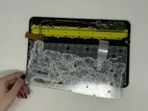
This guide will show you how to replace the flex circuit in your Logitech K480 keyboard. A flex circuit is used as a connector between electrical components when saving space and flexibility are most important in a device. A flex circuit might need to be replaced if the components are not connecting properly or if the circuit is damaged. The circuit is fragile and easily torn or bent, so be gentle when handling it.

  1. BpLEuxwteaADLG26
    • Flip the keyboard over.

  2. pwbFBpLQoRl5PEli
    pwbFBpLQoRl5PEli
    N5wHwoHwaCPpQI5f
    gAD5YBiuHFPHSELC
    • Remove the four rubber feet with a spudger.

  3. EHGHVYrkodlBAMSv
    EHGHVYrkodlBAMSv
    BZtAHFh5tjpk4dSB
    6SXfX4VJE1I1C4kM
    • Slide open battery panel.

    • Remove the batteries.

  4. 2r2LLrL6FI1majVF
    2r2LLrL6FI1majVF
    IbT6XagSQQBRXCJh
    • Remove the three 4 mm screws under the rubber feet using a Phillips #0 screwdriver.

  5. YtHgLEpq5qUQqDVD
    YtHgLEpq5qUQqDVD
    TBmejwWsvyfqkNkh
    • Remove the two 4 mm screws from beneath the battery cover using a Phillips #0 screwdriver.

  6. hOOAVNdTiNDGJoPk
    hOOAVNdTiNDGJoPk
    erKNIBlL4cuQCnBT
    IlCi332qfVVKVyXY
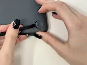
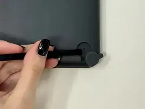
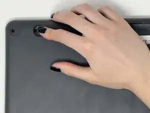
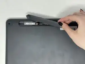
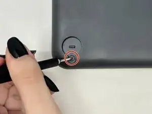
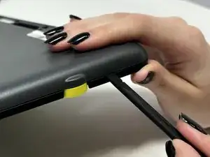
    • Starting by the dial, slide the spudger between the front and back panels until it lifts and snaps.

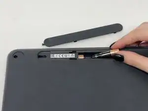
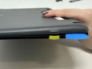
    • Slide a blue pick in to keep the pieces apart while you work on other areas.

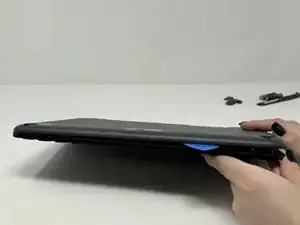
    • Continue prying along the edges until you have enough opened that you can pull both pieces apart gently with your hands.

    • The loud snaps are the clips that hold the pieces together. They're not breaking and you do not need to be alarmed.

  7. WBFnmT2dojemG3fg
    WBFnmT2dojemG3fg
    BduOkhCIIOWpTUGb
    fWLE6ImmFNQNcQJn
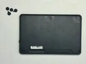
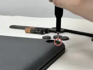
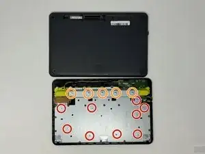
    • Remove the eight 3 mm screws using a Phillips #00 screwdriver

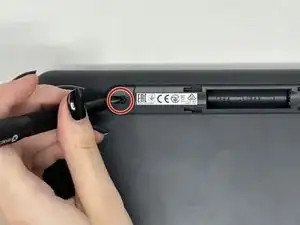
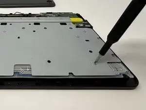
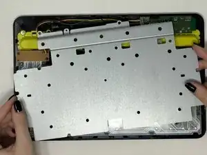
    • Remove the five 2 mm silver screws from the metal plate using a Phillips #00 screwdriver.

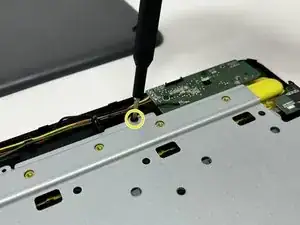
    • Remove the single 4 mm black screw by the motherboard using a Phillips #00 screwdriver.

  8. NZthIFhmqe1eo4ni
    NZthIFhmqe1eo4ni
    4FKamppkyCwJenoN
    • Lift up and remove the metal plate.

  9. HZ13j1MWScgfWxQO
    HZ13j1MWScgfWxQO
    QCEfXkoE6pVFSiyJ
    • Remove the two black 4 mm screws from the motherboard with a Phillips #00 screwdriver.

  10. nGukP5K1NXrrJJ6F
    nGukP5K1NXrrJJ6F
    aCokBibOY24Q1wGA
    • Gently pull the flex circuit from the back of the motherboard.

    • The flex circuit is fragile so be gentle when pulling it out.

  11. RYuDDKRJYHkQQVAT
    RYuDDKRJYHkQQVAT
    eaGmDNlBITwYo6el
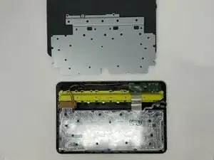
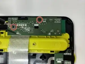
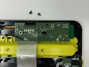
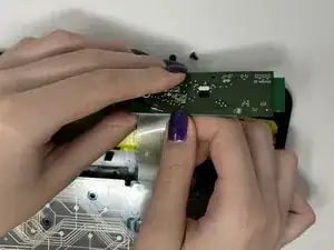
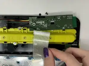
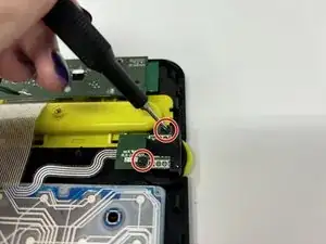
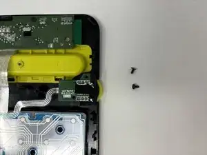
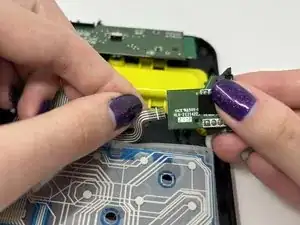
    • Remove the two black 4 mm screws from the dial motherboard below the regular motherboard with a Phillips #00 screwdriver.

  12. UaKt5OHPYrjmRjGO
    • Gently pull the circuit sheet from behind the dial motherboard.

    • The flex circuit is fragile so be gentle when pulling it out.

  13. kE1bylcBb2l3VX2I
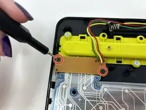
    • Remove the two black 4 mm screws holding the Bluetooth component on the left side using a Phillips #00 screwdriver.

  14. GXQBNXTCpUwpnBFM
    • Lift the flex circuit and remove.

Conclusion

To reassemble your device, follow these instructions in reverse order.

Madison

Member since: 04/09/24

655 Reputation

0 comments