
Introduction
Completely replacing the logic board requires removal of the logic board itself as well as all components attached to it.
-
-
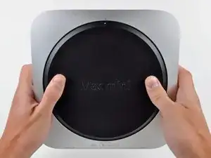
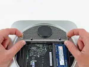
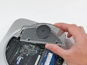
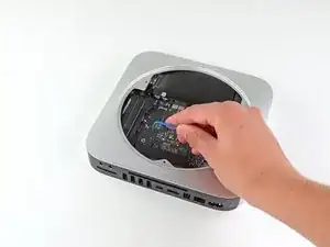
Place your thumbs in the depressions cut into the bottom cover.
-
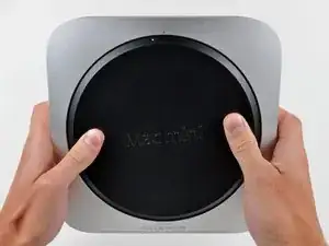
Rotate the bottom cover counter-clockwise until the white dot painted on the bottom cover is aligned with the ring inscribed on the outer case.
-
-
-
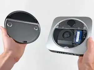
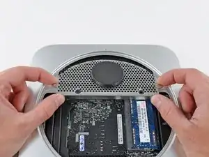
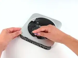
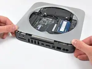
Tilt the mini enough to allow the bottom cover to fall away from the outer case.
-
Remove the bottom cover and set it aside.
-
-
-
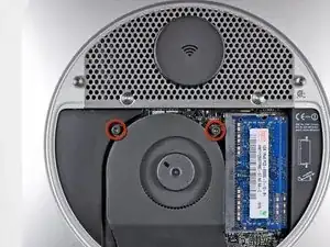
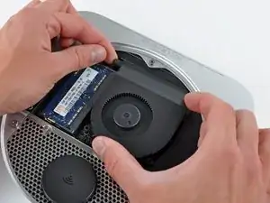
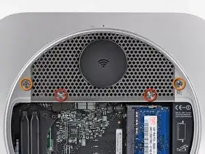
Remove the two 11.3 mm T6 Torx screws securing the fan to the logic board near the antenna plate.
-
-
-
Lift the fan out of the mini for enough clearance to access its connector.
-
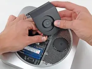
Carefully pull the fan cables upward to lift the fan connector up out of its socket on the logic board.
-
Remove the fan.
-
-
-
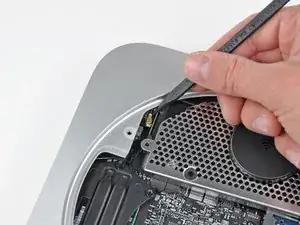
Lift the cowling from the end nearest the antenna plate.
-
Rotate the cowling away from the outer case and remove it from the mini.
-
-
-
Remove the following screws securing the antenna plate to the mini:
-
Two 6.6 mm T8 or T9 Torx screws
-
Two 5.0 mm T8 Torx or 2.0 mm Hex screws (either will work)
-
-
-
Slightly lift the antenna plate from the end closest to the RAM.
-
Carefully pull the antenna plate straight away from the circular rim of the outer case.
-
-
-
Use the tip of a spudger to carefully pry the antenna connector up off the AirPort/Bluetooth board.
-
-
-
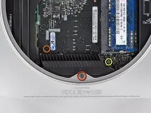
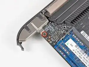
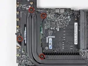
Remove the following three screws:
-
One 5.0 mm T8 Torx or 2.0 mm Hex screw (either will work)
-
One 16.2 mm T6 Torx screw
-
One 26 mm T6 Torx standoff
-
-
-
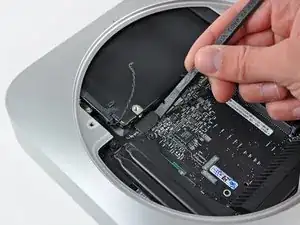
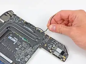
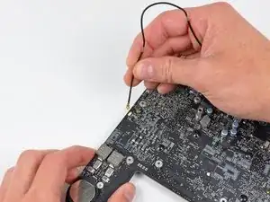
Carefully pull the wires for both hard drive thermal sensors upward to lift their connectors up and out of the sockets on the logic board.
-
-
-
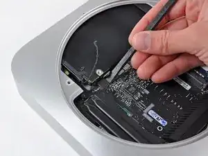
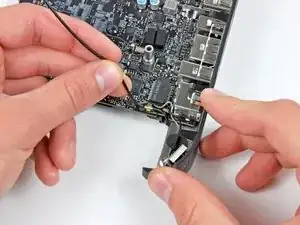
Use the flat end of a spudger to pry both the hard drive and optical drive connectors up out of their sockets on the logic board.
-
-
-
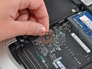
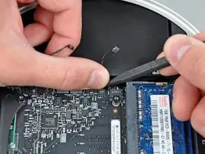
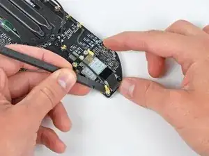
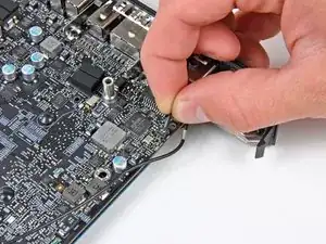
To disconnect the optical drive thermal sensor, pinch its cables between your thumb and a spudger and pry the spudger upward to lift the connector up and out of its socket on the logic board.
-
-
-
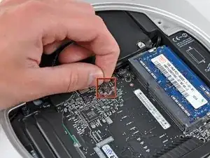
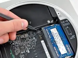
Use the tip of a spudger to lift the IR sensor connector up and out of its socket on the logic board.
-
-
-
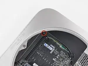
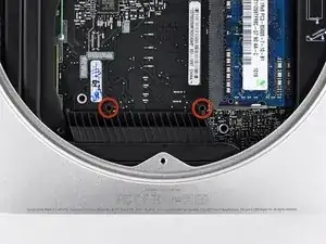
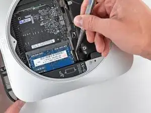
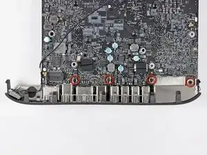
Insert a Mac mini Logic Board Removal Tool into the two holes highlighted in red. Be sure it makes contact with the outer case below the logic board before proceeding.
-
Carefully pull the tool toward the I/O board. The logic board and I/O board assembly should slightly slide out of the outer case.
-
Cease prying when the I/O board is visibly separated from the outer case. Remove the Mac mini Logic Board Removal tool.
-
-
-
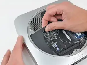
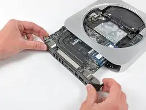
Simultaneously push the two plastic clips on the far left and right sides of the I/O board toward the middle of the I/O board and pull the I/O board away from the outer case.
-
-
-
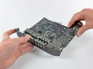
Carefully slide the logic board assembly out of the mini, minding any cables that may get caught.
-
-
-
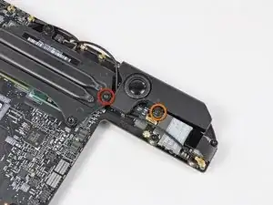
Remove the following two screws securing the speaker to the logic board assembly:
-
One 4.2 mm T6 Torx
-
One 3.7 mm T6 Torx
-
-
-
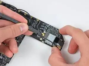
Carefully lift the speaker wires upward to lift the speaker connector up and out of its socket on the logic board.
-
-
-
Use the flat end of a spudger to pry the antenna connectors up off the AirPort/Bluetooth board.
-
-
-
De-route both antenna cables from the clips securing them to the top side of the logic board.
-
-
-
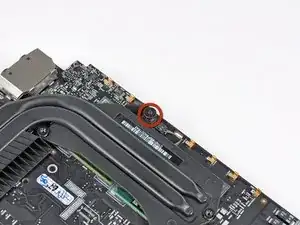
Remove the single 2.6 mm T6 Torx screw securing the I/O bezel to the logic board near the RAM.
-
-
-
Carefully un-clip the antenna from the logic board near the PRAM battery.
-
Gently de-route the antenna cable through the hole in the logic board.
-
De-route the antenna cable from the clips on the logic board near the I/O bezel.
-
-
-
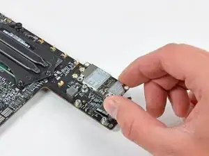
Lift the power button cables upward to gently pull the power button cable up and out of its connector on the logic board.
-
-
-
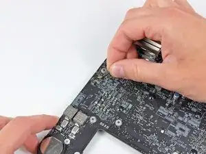
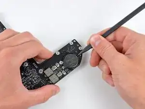
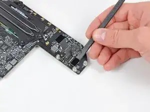
Use the tip of a spudger to carefully pry the PRAM battery up and out of its holder on the logic board.
-
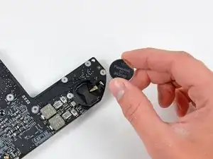
Remove the PRAM battery and set it aside.
-
-
-
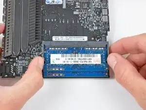
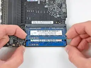
Release the tabs on each side of the RAM chip by simultaneously pushing each tab away from the RAM.
-
After the RAM chip has popped up, pull it straight out of its socket.
-
-
-
Use the flat end of a spudger to pry the AirPort/Bluetooth ribbon cable connector up off the AirPort/Bluetooth board.
-
-
-
Remove the three 2.6 mm T6 Torx screws securing the AirPort/Bluetooth board to the logic board.
-
Remove the AirPort/Bluetooth board and set it aside.
-
-
-
Use the flat end of a spudger to pry the AirPort/Bluetooth ribbon cable up off the logic board.
-
Remove the AirPort/Bluetooth ribbon cable.
-
-
-
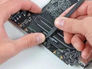
To disconnect the heat sink thermal sensor, pinch its cables between your thumb and a spudger and pry the spudger upward to lift the connector up and out of its socket on the logic board.
-
-
-
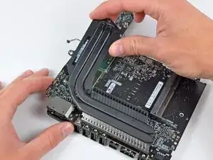
Carefully lift the heat sink off the logic board, minding the thermal sensor cable that may get caught.
-
If you need to mount the heat sink back onto the logic board, we have a thermal paste guide that makes replacing the thermal compound easy.
-


To reassemble your device, follow these instructions in reverse order.

7 comments
I'm confused, in step 11 the antenna plate is removed from the case, then in step 12 the bare logic board is out. What happened to the rest of the removal process?
Hey sorry about that, the guide was missing a prerequisite. I went through and made sure all the guides are OK. It should be fixed now. Good catch!
Does the logicboard of the Mac mini 2011 or 2012 fit in the Mac mini 2010?
Kristian -
I’d really like to know this as well if anyone knows
I'd like to know also
It depends what you mean by “fit”. If you want to put a 2011 or 2012 logic board in a 2010’s case and get the additional optical drive, then no. The 2011 and 2012’s logic boards include capacitors that get in the way of the optical drive, so you cannot re-insert the logic board to fit. The 2010 server model will fit, as the case has the correct dimensions.
Does the Mac Mini 2010 desktop have the same hardware as the Mac Mini server model? Can I swap parts between the two of them?
jkbmjp -