
Introduction
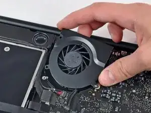
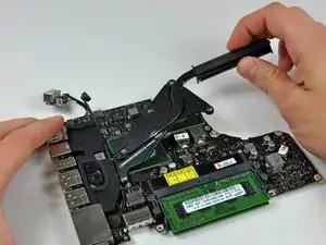
The heat sink helps keep the processor cool and happy.
-
-
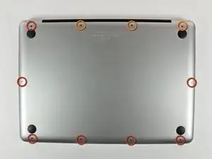
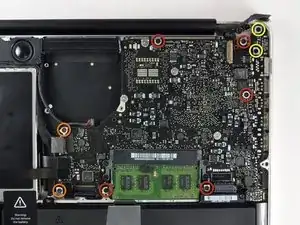
Remove the following 10 screws securing the lower case to the MacBook Pro 13" Unibody:
-
Seven 3 mm Phillips screws.
-
Three 13.5 mm Phillips screws.
-
-
-
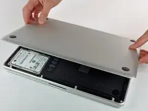
Slightly lift the lower case and push it toward the rear of the computer to free the mounting tabs.
-
-
-
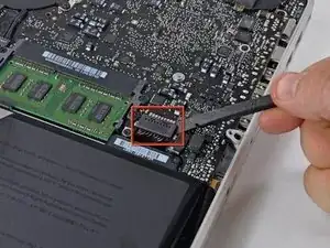
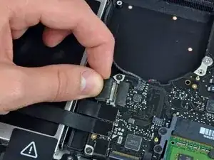
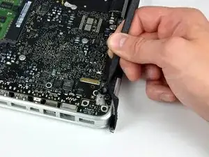
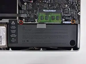
Use the flat end of a spudger to lift the battery connector up out of its socket on the logic board.
-
-
-
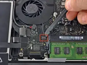
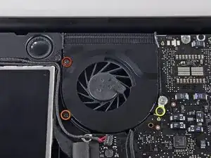
Remove the following three screws securing the fan to the upper case:
-
One 6.5 mm Phillips.
-
One 5.5 mm Phillips.
-
One 4.5 mm Phillips.
-
-
-
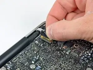
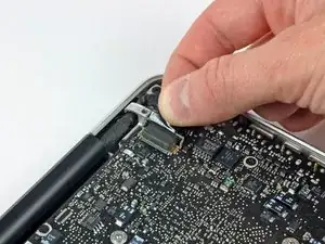
Grab the plastic pull tab secured to the display data cable lock, and rotate it toward the DC-in side of the computer.
-
Pull the display data cable connector straight away from its socket, towards the DC-in side of the computer.
-
-
-
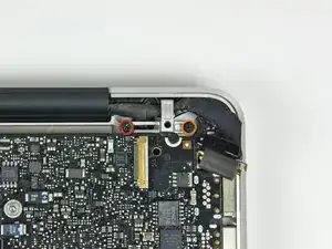
Remove the following two screws securing the display data cable bracket to the upper case:
-
One 7 mm Phillips.
-
One 5 mm Phillips.
-
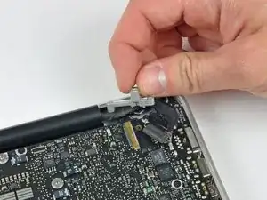
Lift the display data cable bracket out of the upper case.
-
-
-
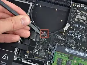
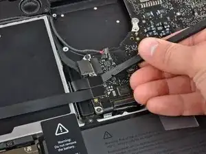
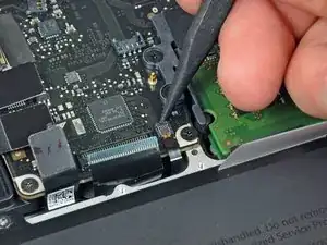
Use the flat end of a spudger to pry the subwoofer and right speaker connector up off the logic board.
-
-
-
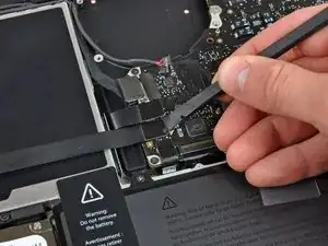
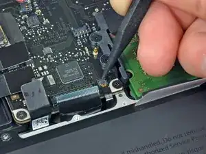
Pull the camera cable connector toward the optical drive to disconnect it from the logic board.
-
-
-
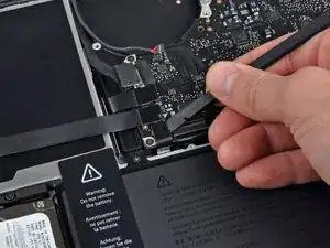
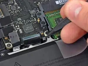
Use the flat end of a spudger to pry the optical drive, hard drive, and trackpad cable connectors up off the logic board.
-
-
-
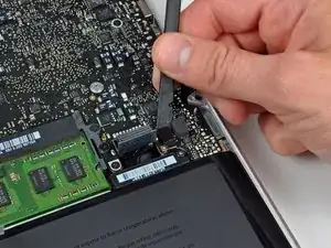
Use your fingernail or the tip of a spudger to flip up the cable retaining flap on the ZIF socket for the keyboard ribbon cable.
-
Use your spudger to slide the keyboard ribbon cable out of its socket.
-
-
-
Use the tip of a spudger to flip up the cable retaining flap on the ZIF socket for the keyboard backlight ribbon cable.
-
Use your spudger to slide the keyboard backlight ribbon cable out of its socket.
-
-
-
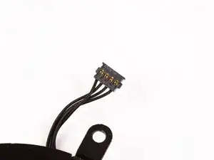
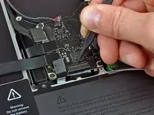
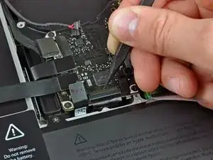
Use the flat end of a spudger to pry the battery indicator cable connector up off the logic board.
-
-
-
Use the tip of a spudger to pry the microphone off the adhesive attaching it to the upper case.
-
-
-
Remove the following screws:
-
Five 3.1 mm Phillips.
-
Two 3.9 mm Phillips.
-
Two 7 mm Phillips from the DC-in board.
-
-
-
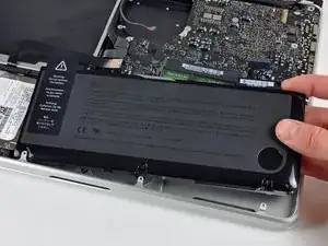
Remove the following Tri-point screws securing the battery to the upper case:
-
One 5.5 mm Tri-point screw.
-
One 13.5 mm Tri-point screw.
-
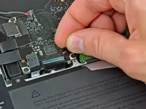
Lift the battery out of the upper case.
-
-
-
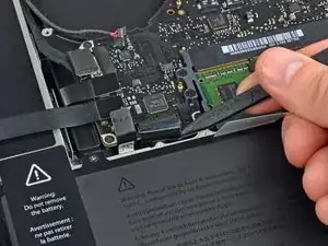
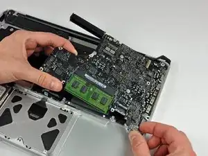
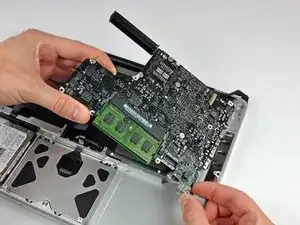
Lift the logic board from its left edge and raise it until the ports clear the side of the upper case.
-
Pull the logic board away from the side of the upper case and remove it, minding the DC-in board that may get caught.
-


To reassemble your device, follow these instructions in reverse order.

4 comments
After completing this process and reapplying thermal paste on my CPU and GPU, CPU Core 1 & 2 temperature sensors were not being read. As a result, my fan was not operating and the CPU diode temperature jumped to >100C.
To fix this I had to reset the SMC (System Management Controller). For this model it is done by holding done Shift+Control+Option and pressing the power button while the computer is off.
I have OS X 10.8.5 running. I also replaced my battery at the same time as reapplying thermal paste. No idea if that affected the temperature sensors.
Followed this guide to change thermal paste on CPU & GPU, all worked fine, now I have >10°C difference. I had a problem on a screw that wore out, solved by cutting a piece of motherboard. I recommend following this guide alongside a youtube guide video, if you are not sure on how to unplug some cables (like in which direction to pull). And as always, double (triple possibly) check that you have reconnected all cables, otherwise you’ll have to go through all of this again.
Well, my computer no longer turns on...reconnected all the cables, was very cautious and followed all steps and now it won't power on...it will charge, just won't power on anymore
Compare the short screws carefully before reinstalling them. The shouldered screws go in the holes on the front edge.
David Kilbridge -
Before I started removing any screws I took a piece of paper and drew the bottom of the laptop and put a piece of double-sided tape in the spot where each screw goes. That way when I took out the screws, I could put them on the tape so I knew exactly which screw went in which spot. I did the same thing for dismantling the inside on another sheet of paper, then a third sheet for the screen after getting the front glass off.
mastover -
I use a similar technique: I print out the iFixit manual for the job, and Scotch-tape down the screws/brackets/cables I remove at each step next to the component descriptions. That way, when I'm reassembling, the bits are taped right next to the photo of where they came from.
adlerpe -
That's exactly what I do for all my repairs! It's the best way to keep track of all of the parts ' original location and to make sure that you don't miss any parts during reassembly.
joyitsjennie -
Great idea and one I use often
Thomas Overstreet -
Excellent idea! Thanks for sharing it here.
Laura Sharkey -
I used a 00 that fit but the screws were very tight so I used a tiny paintbrush with some wd40 on it and put it around the edges of the screws. Worked like a charm
valentinedhdh -
I use a magnetic mat and place the screws in order on that :)
Cary B -
How to tell all screws apart?
Spudgeboy -