Introduction
This guide has been updated by iFixit staff! Read the new, official MacBook Pro 15" Unibody Mid 2010 Matte LCD Replacement guide.
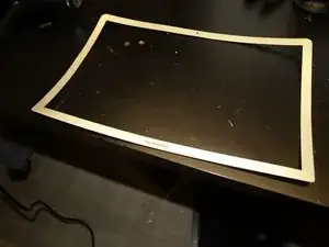
This guide covers removal and replacement of the Matte Finish LCD. Aside from your screen not being glossy or glared, you know you have a Matte Finish LCD if you have an approx. 14mm brushed aluminum bezel around your screen.
Most people DON'T have this bezel, and so should use the existing Glossy LCD replacement guide instead: MacBook Pro 15" Unibody Mid 2010 LCD Replacement .
The display assemblies of Matte Finish LCD and Glossy LCD version of the MacBook Pro differ in a few ways:
- The aluminum bezel.
- The actual LCD is different (Matte finish, of course)
- The exterior glass of the matte display is optically bonded to the LCD, so you cannot remove the glass with suction cups.
Apart from the display assemblies, the Matte Finish LCD Macbook Pro is identical to a Glossy LCD Macbook Pro of the same screen size.
Note that this guide is marked "difficult". The reason it is marked that way is that you will have to remove the bezel, which is thin aluminum, and the display bumper which is a thin piece of rubber. If you damage these parts (i.e. you put a hard bend in the bezel or tear the bumper), you likely won't be able to get another. This is not necessarily a hard to perform procedure, but could be risky. So please read this guide and consider if it is for you before moving forward.
-
-
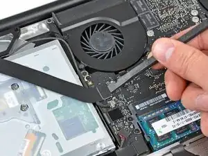
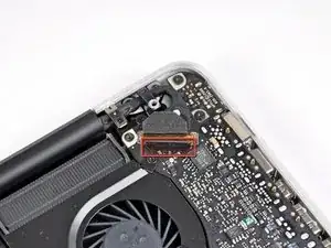
Use the flat end of a spudger to carefully pry the AirPort/Bluetooth ribbon cable up off its socket on the logic board.
-
-
-
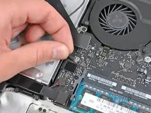
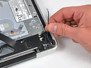
Use the tip of a spudger to pry the three antenna connectors up off the AirPort/Bluetooth board.
-
-
-
De-route all three antenna cables from their channels in the AirPort/Bluetooth housing.
-
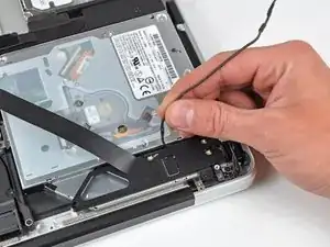
De-route the camera cable from its channel in the AirPort/Bluetooth housing.
-
-
-
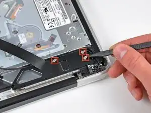
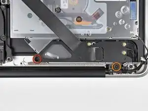
Remove the following two screws securing the AirPort/Bluetooth housing to the upper case:
-
One 3.8 mm Phillips
-
One 8.6 mm Phillips
-
-
-
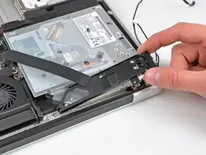
Remove the AirPort/Bluetooth assembly from the upper case, minding any cables that may get caught.
-
-
-
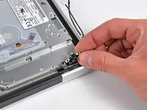
Remove the 8.6 mm Phillips screw securing the antenna/camera cable retainer to the upper case.
-
Remove the antenna/camera cable retainer from the upper case.
-
-
-
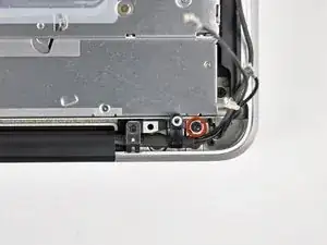
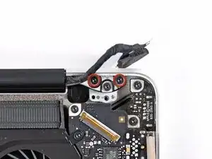
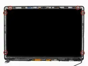
Remove two of the three 6 mm T6 Torx screws securing the right side of the display to the upper case.
-
-
-
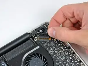
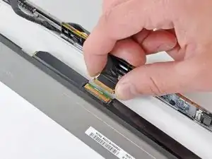
Grab the plastic pull tab secured to the display data cable lock and rotate it toward the DC-In side of the computer.
-
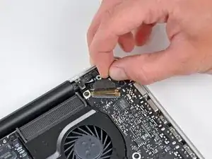
Pull the display data cable straight out of its socket on the logic board.
-
-
-
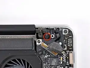
Remove the 8.6 mm Phillips screw securing the display data cable retainer to the upper case.
-
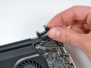
Remove the display data cable retainer from the upper case.
-
-
-
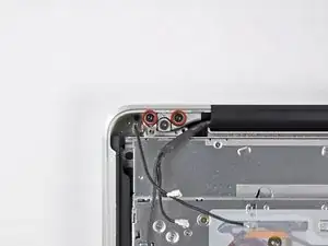
Remove two of the three 6 mm T6 Torx screws securing the left side of the display to the upper case.
-
-
-
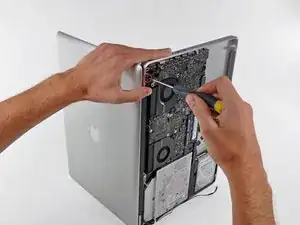
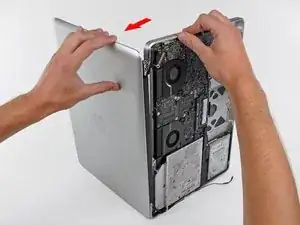
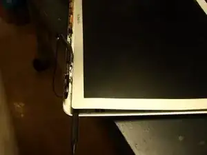
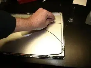
Open your MacBook Pro so the display is perpendicular to the upper case.
-
Place your opened MacBook Pro on a table as pictured.
-
While holding the display and upper case together with your left hand, remove the remaining T6 Torx screw from the upper display bracket.
-
-
-
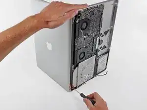
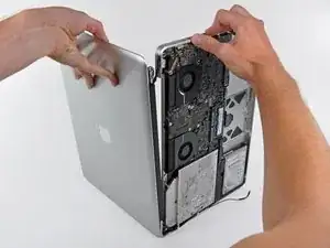
Grab the upper case with your right hand and rotate it slightly toward the top of the display so the upper display bracket clears the edge of the upper case.
-
Rotate the display slightly away from the upper case.
-
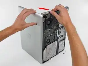
Lift the display up and away from the upper case, minding any brackets or cables that may get caught.
-
-
-
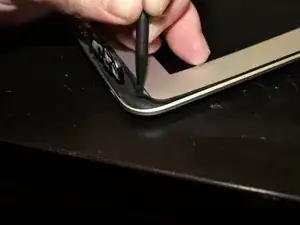
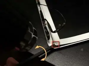
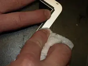
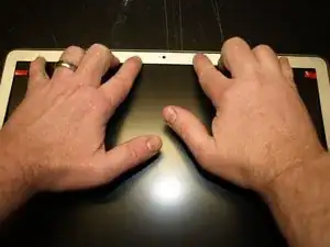
At the bottom right corner of the screen, insert the pointed side of spudger between the bezel and wide, flat part of rubber bumper. Pull the bumper towards to hinge to release the adhesive.
-
Then place the flat side of the spudger between bezel and bumper at the same location, slip the spudger underneath the bumper and lift.
-
-
-
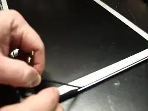
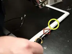
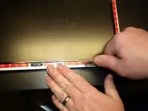
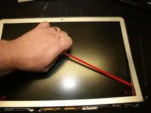
Moving up the right side of the screen, begin pulling the bumper out slowly, in approximately 1"-2" increments. Continue around the screen until the bumper is complete removed.
-
-
-
While applying heat with a heat gun:
-
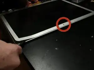
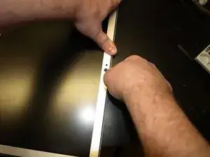
Place the flat edge of the spudger under the bottom lip of the bezel on the lower right portion of the display assembly.
-
Gently pry the corner of the bezel upward, creating enough space to insert the flat edge of the spudger between the bezel and display assembly.
-
With the flat edge of the spudger under the bezel, gently twist the spudger to release the double stick adhesive tape.
-
-
-
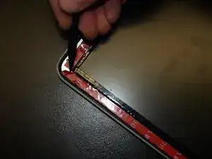
Continue working up the right side in 1"-1.5" increments:
-
Apply heat to the unreleased area.
-
From the outer edge of the bezel, insert the flat side of the spudger to where it snugly fits under the lifted portion of the bezel.
-
Gently twist the spudger.
-
-
-
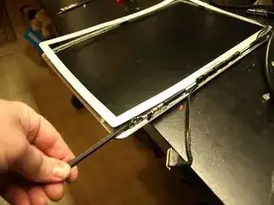
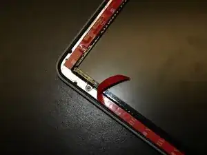
Continue the technique described in the previous step to release the bezel along the top and on the left side.
-
-
-
To release the lower left of the bezel, while applying heat, insert the flat end of the spudger from the left side, and gently twist to pry up the double stick tape.
-
Repeat above from the right side to release the lower right.
-
-
-
Remove the bezel from the display assembly.
-
Clean the bottom side of the bezel with isopropyl alcohol and set it aside.
-
-
-
Remove the LCD following steps 33-36 of the guide: MacBook Pro 15" Unibody Mid 2010 LCD Replacement .
-
-
-
Reinsert the rubber bumper into the display assembly, taking care to align the tabs to the tab indentations in the flange.
-
With a cotton swab, clean any excess adhesive off with isopropyl alcohol.
-
-
-
Install new LCD following steps 36-33 of the MacBook Pro 15" Unibody Mid 2010 LCD Replacement guide in reverse.
-
-
-
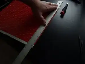
Get the 12x12 sheet of 3M 4905 VHB Tape, place it on the table, red adhesive backing up, with the overhanging white adhesive backing on the top and bottom.
-
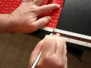
With a ruler, measure and mark 3mm from the right edge at the top and bottom of the 4905 sheet.
-
-
-
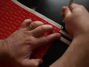
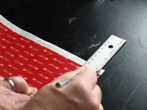
Place a metal straight across the sheet, aligned with the two 3mm marks made in the previous step.
-
With the X-acto knife, cut a 3 mm wide strip of adhesive.
-
-
-
Repeat steps 7 and 8 one more times for an additional 3mm wide strip.
-
Then perform steps 7 and 8 three more times with 6mm measurements.
-
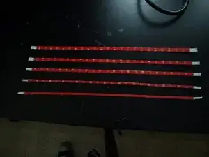
This should yield a total of:
-
Two 3mm x 12in 4905 adhesive strips.
-
Three 6mm x 12in 4905 adhesive strips.
-
-
-
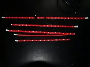
Trim one of the 6mm strips:
-
One 6mm x 120mm
-
One 6mm x 30mm
-
One 6mm x 155mm
-
Trim each of the other two of the 6mm into 6mm x 230mm strips.
-
Trim the each of the 3mm strips into 3mm x 170mm strips.
-
-
-
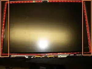
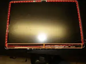
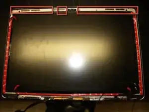
On the display assembly, apply the 6mm x 230mm strips, red side up, to the flange between the bumper and screen on the left and right sides.
-
-
-
Apply the two 3mm x 170mm strips on the flange, red side up, between the bumper and screen at the bottom of the display assembly.
-
-
-
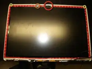
Tooling holes on the left and right upper corners.
-
Camera.
-
EMI Pad
-
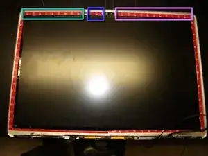
On the flange of the display assembly:
-
Apply the 6mm x 120mm strip, red side up, to the area on the flange between the EMI pad and the adhesive strip on the left side.
-
Apply the 6mm x 30mm strip, red side up, to the area on the flange between the EMI pad and the camera.
-
Apply the 6mm x 155mm strip, red side up, to the area on the flange between the camer and the adhesive strip on the right side.
-
-
-
While applying pressure with the flat side of the spudger, drag the spudger across all of the attached adhesive strips.
-
-
-
On the upper corner of the adhesive on the left side of the display assembly.
-
Slip an X-acto knife between the red backing and
-
Use the X-acto knife to peel enough of the backing so that it can be grabbed with fingers.
-
Peel about one inch of the red backing and fold it to the inside.
-
Do the same for the adhesive on the right side and both adhesive strips on the bottom of the display.
-
For the three strips on the top of the display, peel all of the adhesive backing off.
-
-
-
Carefully align the bezel tooling pin into in the tooling holes at the top of the display assembly. Set the bezel in place and apply pressure.
-
Pull the rest of the red backing strips to expose the adhesive to the rest of the bezel.
-
While applying pressure with the flat side of the spudger, rub around the entire bezel to ensure the adhesive sets properly.
-
-
-
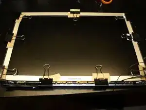
Place binder clips around the bezel to hold it in place. Use cardboard under the clips to keep from scratching the display assembly.
-

After the bezel adhesive has adequately cured, install the display assembly according to the MacBook Pro 15" Unibody Mid 2010 Display Replacement guide.
One comment
Just finished this and here's my 2 cents:
1) If you use guitar picks to pry the bezel out you cant do it inside out. That means no need to mess with that rubber band that goes around it. Also means it wont look as bad (bowed) once you're done removing it;
2) It is aluminium so you can always un-bend the thing and straighten it up just be careful;
3) I realise it probably wasn't available at the time this guide was made but you can use the tape designed to hold thin edged iMac's displays. That's what I did anyway and it worked like a charm no need to bind anything (had one set of those tapes laying around for future project so that was easy to get :P).
Hope that helps :)