Introduction

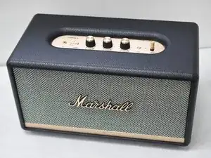
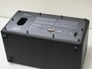
This guide is intended to replace the power switch assembly in the Marshall Stanmore II Bluetooth Speaker.

The power switch turns the speaker on or off while it is plugged into a wall outlet. Over time, the power switch may break or wear down after normal use. This renders the speaker inoperable.

Before using this guide, ensure the speaker is plugged into a working outlet. This can be verified by plugging another device and ensuring that it works as intended. After verifying the outlet, follow the "Failure to power on" section of the Marshall Stanmore II troubleshooting page.

  1. AKWIA1nG1XUe6bJy
    AKWIA1nG1XUe6bJy
    12XgYFFMsALdh2P4
    • Turn off the device and unplug the cable from the wall and the speaker.

    • Lay the speaker with the back panel facing up on a flat, stable work surface.

  2. K1pqyIQbohWadoMI
    K1pqyIQbohWadoMI
    2prEn3HXlrJ6Ry2v
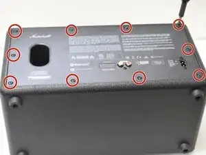
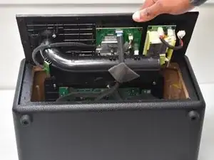
    • Use a Phillips #2 screwdriver to remove the ten 20.5 mm screws that secure the rear panel to the chassis.

  3. vGAAAkbQexnlE2Ab
    vGAAAkbQexnlE2Ab
    IfC1CIotronJCclW
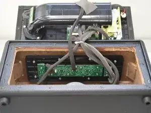
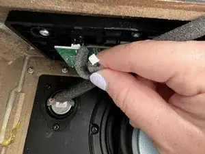
    • Carefully lift the rear panel and let it rest on an object, like a stack of books, to avoid straining the cables.

    • Do not attempt to fully remove the panel, as this will damage the connections inside.

  4. jiI2BhWJ2SVEnbbJ
    jiI2BhWJ2SVEnbbJ
    OsdsqMt1FZxDVZXJ
    UPyNSuPCxwvFPqtk
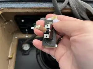
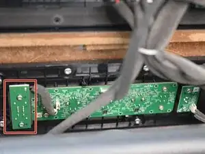
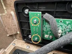
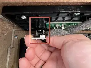
    • Locate the Power Switch PCB on the left-hand side above the subwoofer.

    • Use a Phillips #2 screwdriver to remove the two 10 mm screws that secure the PCB.

    • Because the space inside is somewhat cramped, consider using the iFixit 150 mm Flex Extension included in the iFixit Pro Tech Toolkit.

  5. HjdjQxwBw4koGRNa
    HjdjQxwBw4koGRNa
    nXI2dXD2HOwWtimy
    • Locate the PCB's black wire connector and gently disconnect it.

    • Do not pull on the wires.

  6. oxoYSSyogKaSgoS1
    oxoYSSyogKaSgoS1
    hkiaE3uvB2QIBFmS
    K1UlM43jWkh6ZSLC
    • Pull the PCB out of the mount.

    • Take care not to damage the rubber seal surrounding the switch base as depicted in picture two.

    • Rocking the PCB back and forth while pulling may help remove the module.

Conclusion

To reassemble your device, follow these instructions in reverse order.

Jacob Rose Parks

Member since: 07/02/24

491 Reputation

One comment

Hellooooo very good but were did you fint the eplace the power switch ?

Fred -