Introduction
This guide was specifically created for the Maytag model MDBH969AWW5 dishwasher, but may apply to other models as well.
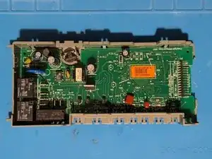
The control board contains all of the control electronics for the dishwasher.
Tools
Parts
-
-
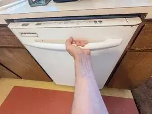
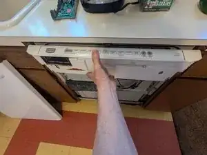
Open the dishwasher door fully until it is laying flat parallel with the floor.
-
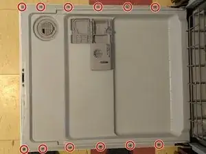
Remove the 12 T-15 Torx screws along either side of the door panel. Save the two nearest the hinges for last.
-
While supporting the front door panel with your hand, remove the two longer T-15 screws on either side of the door latch.
-
-
-
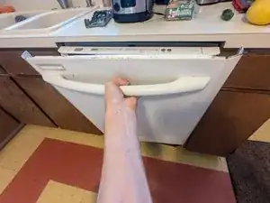
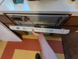
Raise the door back to an upright position, but do not close it fully until it latches.
-
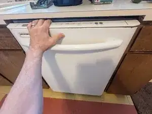
Grasp the door by the handle in preparation for removing it.
-
-
-
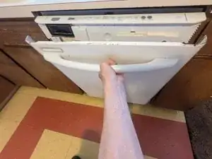
Pull the door panel forward a couple of inches.
-
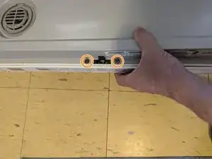
There are two retaining brackets near the hinges on either side of the door panel. Lift the door straight up at least six inches until you clear those brackets.
-
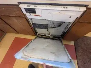
The door panel is now free and can be set aside.
-
-
-
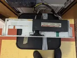
Grasp the control panel and lift straight up to release it from the door.
-
Lay it down in preparation for removing the control board.
-
-
-
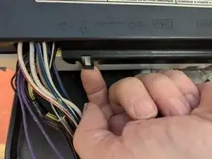
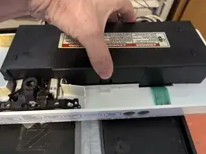
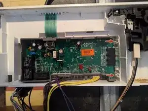
The control board cover is held on by two latches, one on either side. The first one is shown on the opposite side near the bundle of wires.
-
The other latch can be seen directly below my thumb in the second photo; simply press in to release it.
-
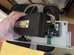
The cover is now free and can be removed and set aside.
-
-
-
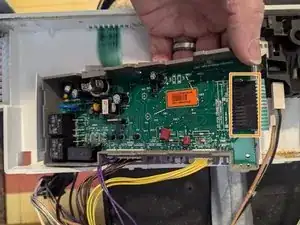
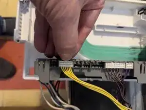
Remove the two wires connected to the Thermal Fuse. Note that they can be difficult to unplug and you may have to hold the fuse down with one hand to avoid pulling it out of its bracket.
-
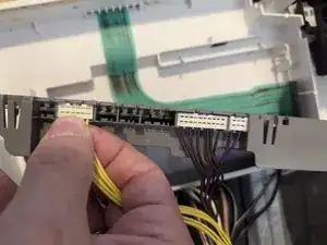
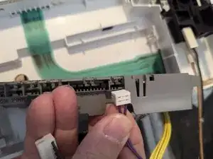
Unplug the two large power connectors by grasping the black plastic part of the connector and pulling straight up on both of them.
-
-
-
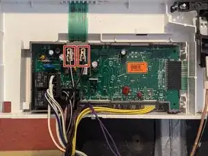
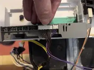
At this point the control board is held in by two latches, seen here being pointed to by red arrows. Releasing both of them will allow you to lift the board from the control panel.
-
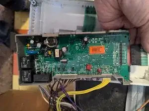
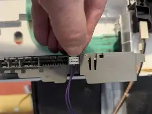
Unplug the touch panel by sliding the connector directly away from the control board.
-
-
-
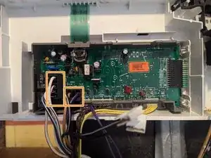
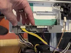
Three edge connectors remain. Flip the board around and set it on edge to access them.
-
Each connector is held in with a single latch; bend the latch slightly then carefully grasp the wires and lift straight up to remove the connector.
-

To reassemble your device, follow these instructions in reverse order.