Introduction
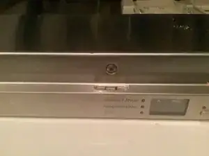
Miele dishwasher G4370SCVi control panel strip AND housing Fixing the control panel finishing strip AND electronics housing. Thi
First a disclaimer:
I only decided to add this to iFixit post mortem, so I do not have detailed pictures of every step! Sorry about that.
Stick with me.
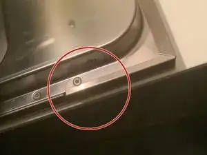
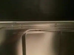
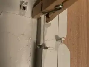
This went from what I thought was something simple to a messy job. The initial problem was that the stainless steel strip covering the controls on the top of the door was loose on the left side so the door could no longer close properly. (I only have the after picture unfortunately). Tried glueing first but that only lasted weeks…
Found this was a common issue and Miele had some parts to fix this.
https://www.mennenwitgoedservice.nl/vaat...
And see images later on.
To install, you had to remove the strip by removing the dishwasher door (kitchen)front, and the hidden row of screws from the outside. Then the control unit housing, make the straight forward repair provided with the parts and voila.
Then I discovered the housing holding the electronics was broken in several places. Without repairing this first it would not work..
Looking at the damage, it looks like someone installed the kitchen panel with the fold in door latch (missing) of the plastic control unit in the wrong position. Once I unscrewed the screw “screwpillars” just disintegrated… Now I was in trouble and doing the dishes by hand…
Tools
-
-
Carefully remove the plastic plugs on the side of the door by prying a sharp knife underneath. Loosen (they remain in place) the torx screws and lift and remove the door panel. Then remove the screws on the metal strip covering the control panel. Remove the strip.upwards!
-
Then remove the screws on the inside of the door holding in the control panel. Don’t forget the 2 on the side. I had a hard time getting the panel out. Careful for the wiring. See below….on dismantling a bit more to make your life easier….
-
Central lock screw is also important, seemed to have a small plastic spacing washer also…
-
During assembly I figured out (my wife actually, ouch) it may be easier to disassemble the whole door by taken all the screws out of the inside edge…..so recommend you do that on disassembly also. All screws if you need to remove/ repair housing, only the bottom 2 x 3 to provide in situ repair.
-
Number all the plugs and their position with permanent marker…unplug all. Careful with the latches on some plugs. Also the plug on the main door latch.
-
Aha, partnumbers, both on labels and in the plastic part…..
-
-
-
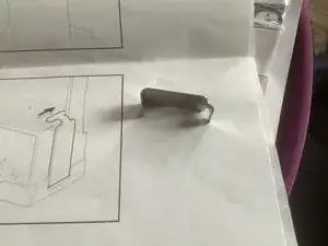
Once the control unit has been detached from the door, you can remove the lock in the middle by carefully inserting smallish screwdrivers in 2 slots to unlatch it.
-
Be careful! The plastic is clearly brittle.
-
You can see the lock holding latches when looking inside from the opposite direction/side.
-
Remove the transparent control buttons cover. 2 small latches at the outer ends.
-
The 2 halves of the control unit housing are held by approx. 6 latches situated around the perimeter AND in the middle section surrounding the lock recess. Again, the plastic was brittle, so be very careful.
-
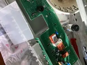
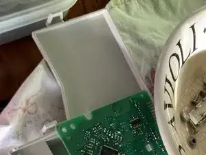
Now you can see the electronics. The main board is held by 2 plastic prongs which you have to squeeze inwards. All surface mount electronics, use plastic tools to reduce the risk of damage. The aux board just slides out.
-
Put the boards to the side in a dry and clean area without too much static. You will need then occasionally to fit your handywork…
-
-
-
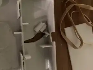
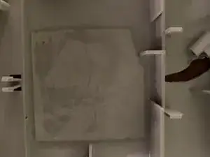
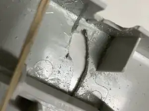
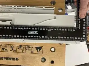
Two large cracks throughout one side of the panel. The through and through ‘pillars’ for the screws are completely gone.
-
Aha, partnumbers, both on labels and in the plastic part….So things are looking good. Until: Miele states only the full assembly is available, including the electronics. 430 Euros.
-
Shock horror. Miele, that is disappointing, this is clearly a) not durable plastic (disintegration) and b) silly a housing is not available. Paying that for a 10 year old machine… no way. Do we junk the dishwasher, or do I do a bush repair? Do I want the challenge?
-
Remember, this disassemby was only to fix the metal strip from coming loose….
-
Someone suggested scan and 3D print, but considering the missing bits, the complex shape and a lack of contacts in that area, I was not confident of success.
-
-
-
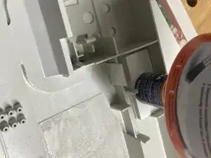
Drilled small holes at the end of the cracks to avoid propagation. Glued the housing first, making sure the housing was flat. There are ribs on the outside, watch where you apply pressure / weight
-
Find some compatible tough plastic (thanks Alberto) and glue it over the cracks. I used both cuts out of an old junction box and a sheet of polyacetate. Tried the glue first to make sure it all bonded. You’ll want to make sure your patches do not interfere with the electronics board, in particular the aux board.
-
Put some patches across the plastic reinforcement ribs, also watching out for how the top half fits on….ensuring no interference.
-
-
-
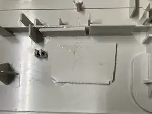
The easy side. no interference with the aux board holding the controls. First, cleanup by removing the remains of the old screwposts. Then I just built up the plastic with small squares polystyrol, 5 mm. About 25 x 35 mm.
-
Glueing them one by one. Roughing up the plastic with some light sandpaper to get max cleanliness and grip. Pvc glue. Getting the height right was a bit of measuring, looking carefully at the other half.
-
The image shows the first 2 layers with some weight on it during glueing.
-
I also made a sample and drilled a few hole sizes to make sure the assembly screws would not be too tight, possibly damaging the repair.
-
I did fill the remaining open hole with some silicone so water could not easily enter the control unit if spilt on the top of the door…
-
-
-
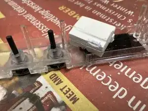
Figure out how it fits in between the aux electronics (in particular the display), the switches (black inpics), the “light” conduits (transparent) and the general molding of the platic cover
-
sandwich 2 each 5 mm layers. Carve as needed. Measure. Carve. Measure again. Think about how the other housing cover fits, the remaining height in between…
-
Make little bushing on top so the screws and stainless strip (dimpled!, mine were initially too high) hit the block and not load the plastic sides.
-
I used a hollow drill for that (thanks Alberto). But drill slowly and in steps, or it will heat up, melt and seize your drill in the plastic. Oeps…
-
-
-
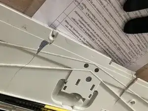
Aligning the holes is key to ensure alignment with the metal finishing strip and avoid undue stresses on the compromised housing.
-
The screws are mostly countersunk on the finishing strips, so the little dimples there reduce the overall height a mm or maybe 2. I underestimated that so had to trim the heights a little again just before final assembly.
-
Getting the hole sizes right: The repair on one side is rickety, quite fragile, because of the small surface to glue onto. So decided to do test samples, drilling between 3 and 3.5 mm, then trying the original screws and how much force was needed to get them in…and how much I could tighten…It’s somewhere in the middle, but I settled on 3.5 mm.
-
Recommend you test with your plastic (hardness would impact) and screws used in the machine.
-
-
-
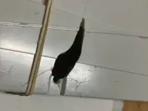
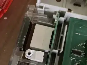
At the last moment I added 2 tiny triangular braces to the difficult side. i was afraid it may break during assembly…making sure it would not interfere with switches, aux board and assembly. One on each side
-
They’re not in this image, but you can easily picture them, there’s not a lot of options. It also shows the small surface this has to hold onto.
-
Put the boards back and carefully clicked the 2 halves together.
-
Clicked the lock back in.
-
-
-
If your housing is in good shape, you can ignore most of the previous blabla. But it has some pointers for the general disassembly and reassembly i did not repeat here.
-
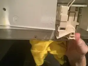
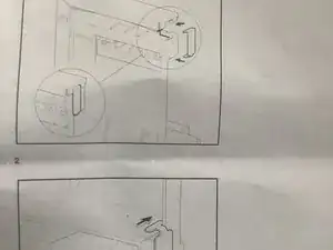
Remove the stainless strip covering the controls (see earlier instructions). Remember it slides up, along a “slide” at each side. That slide bit is the actual broken plastic, which allows the metal strip to move outward…
-
At this point, you may be able to do the small cutting to the “slide” as instructed in the attached Miele instruction without unplugging and removing the housing, depending on your tools (Dremel?). I cannot see how you could add the clips without the removal of the outside of the door as in next step.
-
Remove the rest of the door panel front by releasing all the screws located on the inside of the door bottom, 3 on each side. The additional top ones hold the control panel assy. This will give you space to put the clips in for the repair and, if you need to remove the housing to do the cuts to the housing, make it easy to remove and reassemble.
-
You will see quite some insulation material that kind of wants to come out, but generally it stays in place. Its a bit finicky to put it back during assemby, but with a pair of extra hands, all will be ok.
-
-
-
So it depends how far you had to take it but generally re-assemble in the reverse order
-
Tricky parts for me were (ignoring the crafting of the spacer block)
-
aligning the central door lock and small washer
-
Getting the insulation in place while mounting the outside door panel.
-
Not breaking more plastic
-
Understanding how the Miele fix would work and how I could get it in (remeber I had not removed the full outside panel of the door
-
The weight of the kitchen front was missing, so the door kept bloody closing. We put a large piece log to keep it down when needed
-
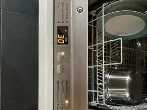
Tested and …..working.
-


In hindsight if I would have disassembled things a bit more early on ( listening to the wife), re-assembly would have been easier, but once discovered, all went smooth. It’s a bummer that Miele only sells the whole assembly at 430 euros . For a silly piece of broken plastic. And the plastic is way too brittle for this application (heat cycles, movement/twisting).
But the primitive repair end result was very satisfying and I am having a large beer to celebrate success. And 430 in the bank.
Ok, well, to be honest, I spent 15 euros on the part, and 8 euros on plastic sheet.