Introduction

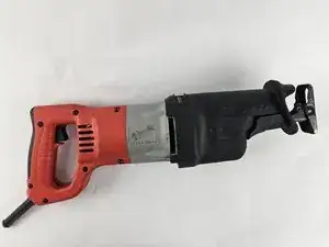
Use this guide to replace the motor of the Milwaukee Sawzall 6520-21. The motor regulates the amount of energy required to operate the saw. This guide's prerequisite is the trigger replacement.

The tools required are the screwdriver handle and the size 20 Torx bit.

  1. CqKGEbvGifkJQZKp
    CqKGEbvGifkJQZKp
    JnmIMKZdtoCESK2j
    aRGai4lo3WvdkPxE
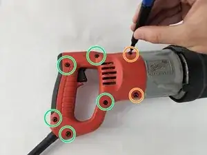
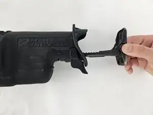
    • Unplug the Sawzall and Orient the right half-handle to face upwards.

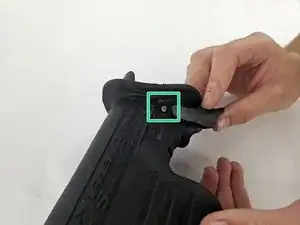
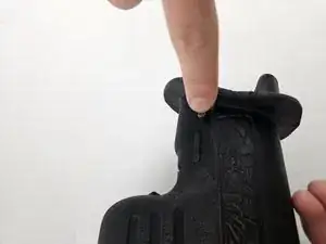
    • With a T20 Torx screwdriver, remove the following screws:

    • 7-18 x 1.125-inch Slt. Plastite T-20

    • 8-16 x .625-inch Slt. Plastite T-20

    • The right-half handle does not contain any wires on the underside.

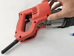
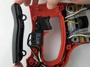
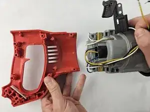
    • Lift the handle off.

  2. 2dZyLZkULuCtThK5
    2dZyLZkULuCtThK5
    Pt42oEaToQl1j5bt
    • Two rubber rings around the divots hold the cushion grip to the handle.

    • Lift off the cushion grip.

  3. BffUlEGiRNHTXH2g
    BffUlEGiRNHTXH2g
    LUAhWoIrpuBvwHG3
    • Remove the screw above the trigger.

    • 8-16 x .625-inch

    • The trigger wires threaded through the handle are not fastened. They do not require any tool to pull out.

  4. FRpY1YJQCxAEqR2Y
    FRpY1YJQCxAEqR2Y
    mHT4JNjMvEcGaVYG
    JKWixYAaiRIKpq2A
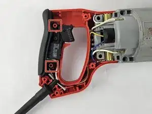
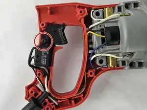
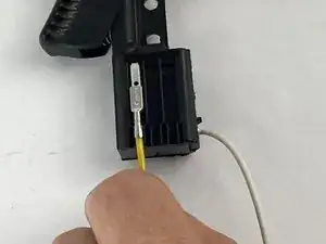
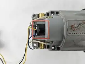
    • Take a 1.5mm flathead screwdriver and insert it into the pin lock above each of the wires:

    • Black wire: Insert it on the left side of the pin. Pull the wire while gently rotating it clockwise

    • Black wire: Insert it on the bottom side of the pin and gently rotate it counterclockwise

    • White wire: Insert it on the right of the pin and gently rotate it counterclockwise

  5. cWSOI2iuKwAxDYBW
    cWSOI2iuKwAxDYBW
    NRZfPIdrHxJcqVfL
    • Gently pull the yellow electrical wire.

  6. AYpBNaWTSTfUkYsT
    AYpBNaWTSTfUkYsT
    rlYZQnXLJ4YRUaPs
    m5TvbGukqRLVqQbV
    • The left half handle and motor housing can separate without difficulty.

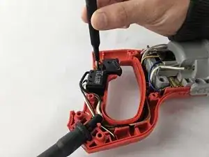
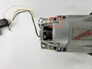
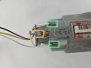
    • The trigger paired with the motor housing wire requires two removals.

    • Gently remove both white wires.

  7. HmORB2MEWFiCFRWY
    HmORB2MEWFiCFRWY
    5iGSafPMm13tGxtG
    r1aNEZLF5tuxtoBR
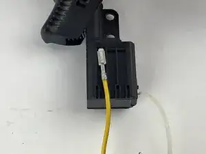
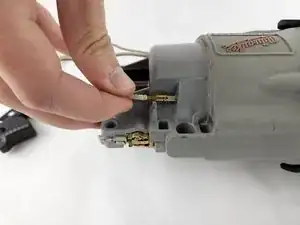
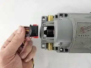
    • Gently slide the following from the motor housing:

    • Black chip.

    • Blue electrical wire.

    • Two, white electrical wires.

  8. VvDyWT2RRHGkfgAu
    VvDyWT2RRHGkfgAu
    MKOeQhtxRKsLeKyM
    fsPBSTLdmJhARmWR
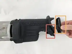
    • Set the shoe release lever in its unlocked position.

    • Remove the shoe assembly.

    • There is a pin that holds the shoe release lever

    • Detach the lever.

  9. quPWquNhgvyfM4Pd
    quPWquNhgvyfM4Pd
    hL5OCLJQ2lDhIlsA
    2tACc1uitHYIC5A6
    • Push or pull the shoe pin to remove it from the gear case insulator.

    • Remove the insulator.

    • This requires a lot of force to remove. It's recommended to have help from another person.

  10. mTV1ACPYGmMVRywU
    mTV1ACPYGmMVRywU
    WG4LswpoHSlDcQNx
    6A2kASdVEFWYEYNB
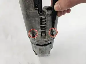
    • Use a T20 Torx screwdriver to remove the following four screws from the gearcase:

    • K50 x 60 mm Washer Hd. PT Screw

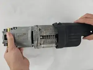
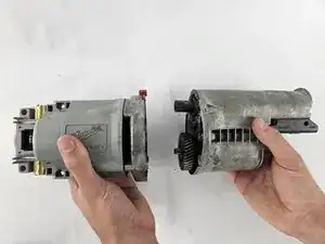
    • Detach the motor housing from the gearcase.

Conclusion

To reassemble your device, follow the above steps in reverse order.
Take your e-waste to an R2 or e-Stewards certified recycler.
Repair didn’t go as planned? Try some basic troubleshooting or ask our Answers community for help.

Garret Haub

Member since: 28/10/24

401 Reputation

0 comments