
Introduction
This guide provides clear instructions to replace the charging port on a Motorola Moto G Power (2020). If your device is not charging properly or has connectivity problems, this repair will help restore its functionality. Before starting, visit our trouble shooting page to rule out other issues.
Additionally, use the Rescue and Smart Assistant app to back up your data and determine whether the problem is hardware or software-related.
Ensure that your workspace is free of static and clean to avoid significant damage to electronic parts.
Why This Repair May Be Needed:
- your device cannot charge and is useless even using a working cable
- the port is damaged or loose
- while charging, the port repeatedly connects and disconnects
Hazards and requirements:
- Handle with safe care, preventing external or internal damage
- Before starting, make sure to disconnect the battery
Preparation:
To ensure that all critical data and information are backed up, use the rescue and intelligent assistant app created by Motorola in case any damage occurs during the process.
By following the steps for the procedure carefully, you can replace your device's charger port and boost its function.
Tools
Parts
-
-
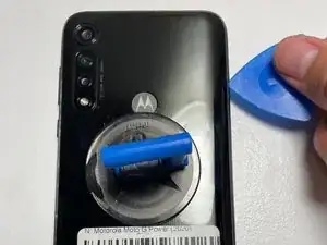
Position a suction cup securely on the back panel of the device.
-
Insert the opening pick into both sides of the phone and carefully slide it along to open the back panel of the device.
-
-
-
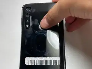
Apply gentle pressure to the fingerprint sensor with your finger to detach it from the back panel.
-
-
-
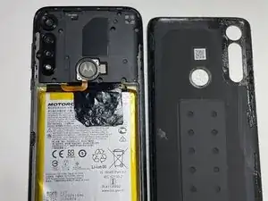
Using the tool T3 Torx screwdriver user must carefully remove 3 1.8mm screws helping to secure the part.
-
-
-
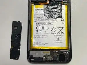
In order to not damage the devices components slowly lift the bottom cover using a needed tool the spudger.
-
-
-
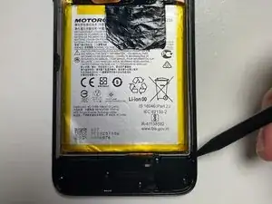
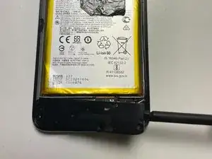
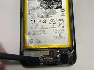
Carefully pry the metal connectors that are attached to the cables with the sudger
-
secondly, on the right side of the device slowly disconnect the two cables from the charge port.
-
-
-
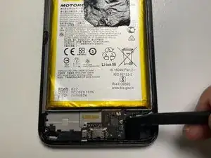
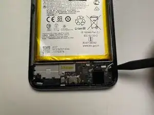
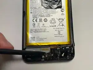
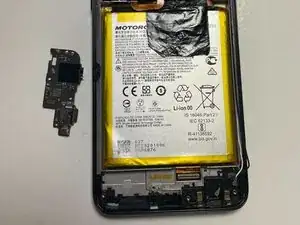
Using a spudger carefully raise the charging port out of your device
-
Light pressure needed to loosen the adhesive
-
To reassemble your device, follow these instructions in reverse order.

3 comments
This guide is good, but understates the ease of taking the back off. There is adhesive holding it on, and it took a heat gun and a LOT of force to pry it open. I only found out when I was trying to tell which of the two shell grooves I needed to pry open (the back one, since there's no side view) and found a different guide on Youtube, and saw them using a heating pad. I also couldn't tell WHICH 3 screws of the 5 were necessary to remove, so I just did all 5. Some circling would help!
Outside of that, thank you so much for the guide, I fixed my first phone all by my self! Minus borrowing my dad's heat gun and the two of us working together to pry the case open, seriously that was the hardest part. Once the case is open, the rest is EASY!! Now to get the dang case back on...
You did not show how to connect the broken charger port do u soder it in or what I'm looking into this
Is the OEM charging port board REV_A or REV_B type? Most available replacement parts I see are REV_B type, but I also see comments about audio output and cellular antenna problems with this type.
I am finding it extremely difficult to find an insertion point between the casing and the screen. I've even brought a Stanley No. 199 Utility knife into play. Still, no separation. These instructions should include the use of a heat gun to soften the adhesive that holds the case and screen together. I may have to bring this to a cell phone repair shop.
Jerry Weinhausen -
Light heat with a blowdryer/heatgun will help it flex more, but you can do it this way. It's definitely challenging as you have to pull on the suction cup close to the edge and you might only get like .5mm of gap.
If you don't have a good spudger or thin piicks like in the picture, heat gun is absolutely necessary.
Zach M -
One thing to note: be careful with a spudger or prying near the right side of the phone. A small wire runs from top to bottom of the phone about 5mm past the phone edge. You can see it in the pictures, it's a black wire that's very tiny. It's easy to see in Step 7 where it connects to the board above the right corner of the battery.
Zach M -
I had a terrible time with the adhesive on the back cover, I lost most of the black film around the camera lens and some around the middle of the bottom edge. I put modest effort towards reinstalling the touch sensor into the back cover, but since I use an external case I did not go overboard. I did test the touch sensor before firmly seating the back cover into the remaining adhesive.
Richard Ekblaw -