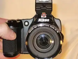
Introduction

The device ports on a digital camera can be prone to damage that may render them nonfunctional. This guide will lead you through the necessary steps to replace damaged device ports.

  1. FSTCFNP5wICffFUe
    FSTCFNP5wICffFUe
    U5PNqESiVh3dEtpG
    Ncj3DDkl6GWjgWNH
    • Remove the battery before beginning.

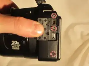
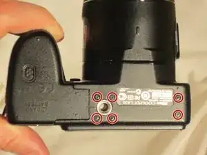
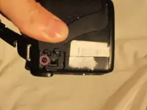
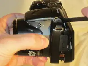
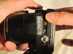
    • Use a Phillips #0 screwdriver to remove the screws on the front casing. There are 10 screws around the casing. 3 are located on the left side of the camera, 6 are located on the bottom near the product label, and 1 is located on the right side of the camera.

  2. 6nOR5LUZcdETj1KJ
    6nOR5LUZcdETj1KJ
    IAZsZjNZQBf2MVbE
    • Next, remove the screw held on top of the camera above the Nikon logo.

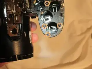
    • Moving to the bottom of the camera, open the empty battery slot, and locate the 4 screws in the compartment. Begin removing the 4 screws located within.

  3. IkuvIyFUMhZET12q
    IkuvIyFUMhZET12q
    YOIEmINCSKuXGsE5
    djomqIrCiEfaZwBp
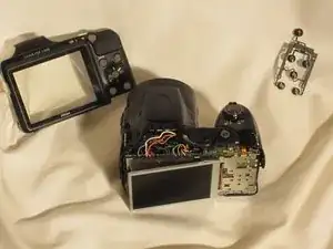
    • Using the spudger, begin prying the case from the device, carefully separating the rear housing from the camera assembly. Once the rear housing is separated, the camera's physical buttons will be accessible for replacement.

    • Be sure to only apply pressure to the casing panels, not internal electronics. Doing so can damage the internal components of the camera.

  4. FSO3irhshgsSyT3j
    FSO3irhshgsSyT3j
    Mu1sRkWlA2TOfQlE
    jVOqFxjhaKyBP1Gf
    • Remove the front casing around the LCD screen from the camera.

    • Avoid putting pressure or moving the exposed wires. This can damage them and cause lasting issue to the camera.

  5. KYFI2mMRKxuCWyTs
    KYFI2mMRKxuCWyTs
    XbclNRTbdJT3HVYS
    QlNFDGnpYjvMrTHk
    • Using the tweezers shown in the materials list, lift the hinges connecting the two ribbon wires to the camera. The wires will unlatch from the device.

  6. lQR64fLU5wISwnBM
    lQR64fLU5wISwnBM
    MkH21XCfHYHnqqpn
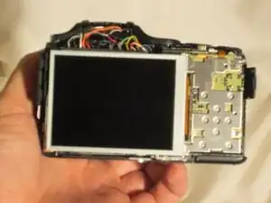
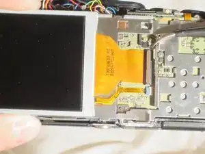
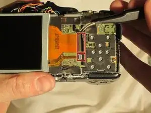
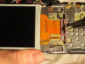
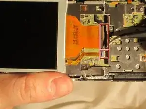
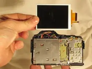
    • Once the ribbon wires are disconnected, remove the LCD screen from the camera.

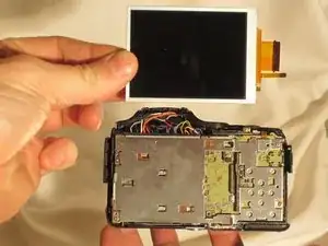
    • Safely store the LCD for reinstallation.

  7. xvDHLckIul1CGXqM
    • Begin by removing these five screws

  8. xtbCXiGZXo1flBKY
    • From there, the panel covering the motherboard can be removed.

  9. KJKEHQ1PQxHkUKXg
    KJKEHQ1PQxHkUKXg
    5y3nBRQoNEy3tylr
    • Using the pointed end of the spudger, lift the hinges that secure these four flex circuits.

  10. j3rfAuCPeNTilMVc
    j3rfAuCPeNTilMVc
    qDST1cwjUF6dEIDG
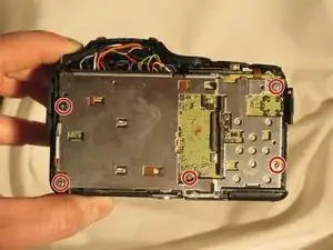
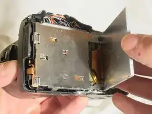
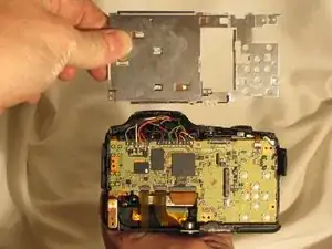
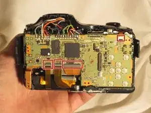
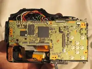
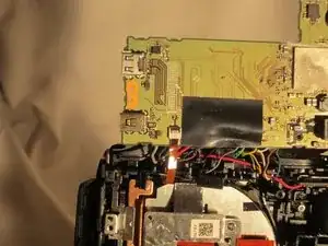
    • Once the flex circuits are removed, the motherboard can be lifted and the device can be accessed for replacement.

    DO NOT “just lift the motherboard"! The motherboard is soldered to a daughterboard for the power button and for the battery compartment. If you do forcibly lift the motherboard you will rip some solder pads off. You need to desolder the motherboard from the daughterboard FIRST before attempting to flip up the motherboard. AFTER desoldering the motherboard there is a singular screw holding in the board in the top left, remove that too!

    Braxton -

Conclusion

To reassemble your device, follow these instructions in reverse order.

Marc

Member since: 23/03/15

430 Reputation

One comment

Could you explain how the power button is changed? Thank you!!

minigalinda -