
Introduction
The purpose of this guide is to replace the eyepiece (plastic rectangular piece around the viewfinder) of a Nikon Coolpix P90 if it is loose, broken, or lost.
In steps 3-4, 6-7, and 9, there are three data connection ribbons which need to be carefully removed before the repair can continue. Failure to remove these ribbons properly will result in them becoming damaged or ripped, thereby permanently damaging your camera. So, please be careful and go slowly during this repair. Take a look at this guide on Recognizing and Disconnecting Cable Connectors for helpful information on safely disconnecting the connectors in this guide.
Before you begin this repair, be sure that your camera is off, the battery is removed, and it is disconnected from the charger.
-
-
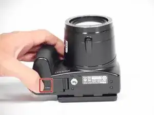
Use your finger to push the latch of the compartment door to the center of the camera body, per image 1.
-
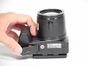
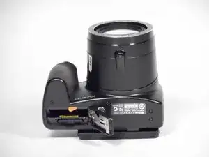
Push the door open, and remove the existing battery with your fingers, per images 2-3.
-
-
-
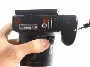
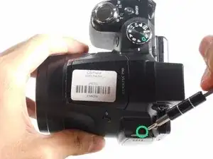
On the bottom side of the camera, remove two 4.5 mm screws holding the bottom case in place.
-
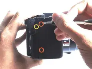
On the right side of the camera, remove two 4.5 mm screws.
-
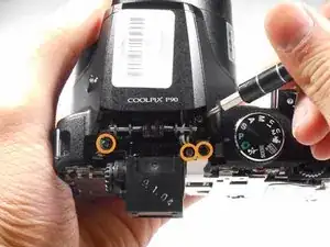
On the right side of the camera, remove the single 4.5 mm screw underneath the A/V flap.
-
On the top of the camera, remove the 4.0 mm screw on the left-side wrist strap loop.
-
-
-
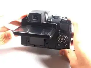
Lift up the LCD screen to reveal the two screws.
-
Use a Phillips #000 screwdriver to remove the two 3.0 mm screws that hold the arm in place.
-
-
-
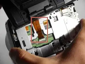
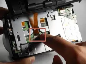
Use a spudger or a clean fingernail to flip up the locking flap on the ZIF connector. This is the unlocked position.
-
Use tweezers or your fingers to gently pull the cable out of its socket.
-
-
-
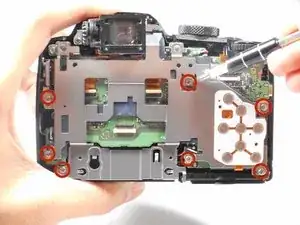
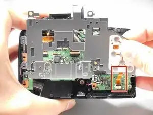
On the back side of the camera, remove the seven 4.0 mm screws that connect the metal plate to the motherboard.
-
On the top side or the camera, remove the three 4.0 mm screws that connect the metal hinges to the camera body.
-
-
-
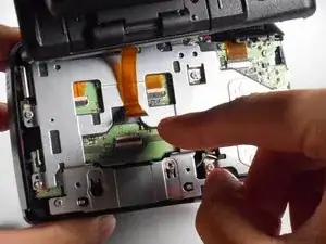
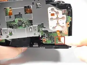
Use a spudger or a clean fingernail to flip up the locking flap on the ZIF connector. This is the unlocked position.
-
Use tweezers or your fingers to gently pull the cable out of its socket.
-
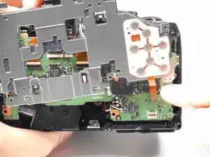
Remove the metal bracket from the camera.
-
-
-
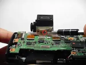
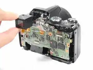
Use a plastic opening tool or spudger, carefully unlock the safety latch that holds the eyepiece data transfer ribbon in place.
-
Slide the ribbon out from its socket.
-


To reassemble your device, follow these instructions in reverse order. Take your e-waste to an R2 or e-Stewards certified recycler.
One comment
Excellent Illustrative photographs and instructions