Introduction

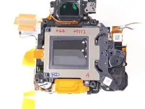
Use this guide to replace the shutter assembly.

Note: You'll need JIS screwdrivers for this repair. Regular Phillips screwdrivers have a cross pattern with rounded inner edges and won't fully fit the slots in the JIS screws. JIS screwdrivers instead have a straight cross pattern which makes much better contact with the screw head and is made for the high torque you will need to loosen the screws.

  1. cm2ORulUQgTIcLmD
    • When loosening the screws, start pressing the screwdriver firmly for the first 1-2 turns (highest torque) until the screw is 'unlocked'. Failing to do so can damage the screw head and make it impossible to disengage that screw.

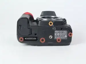
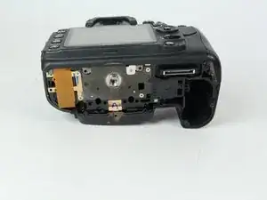
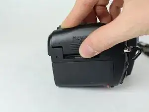
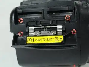
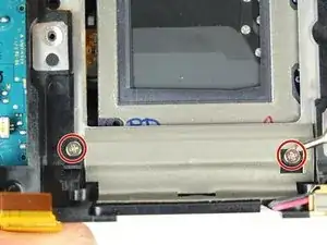
    • Remove the following 5 screws securing the bottom cover to the camera body:

    • Four 6 mm J000 screws.

    • One 8 mm J000 screw (under lens mount).

    Note for D7100: the rightmost screw marked red is 5.4mm long (to the right of the identification sticker with serial number), the 3 other screws marked red are 6.0mm long. The orange screw is 8.75mm long.

    Olivier Biot -

  2. QrvtqxRGqmKLmUBP
    • Remove three 6 mm J000 screws from under the battery cover.

    Note for D7100: the screw marked red closest to the yellow battery guarding clip is 5.3mm long, the 2 other screws marked red are 6.0mm long.

    Olivier Biot -

  3. 1GCOjoFZbEViDOW4
    1GCOjoFZbEViDOW4
    PJGgX3SaLO4TUbMl
    • Gently pull the bottom cover off of the camera body.

    Note for D7100: place your thumb in the battery compartment and your index outside the battery box. Gently pinch the bottom cover between thumb and index finger, and gently lift it from the camera body. It separates very easily.

    Olivier Biot -

  4. XVgnRPoHTfHutPvM
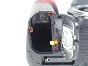
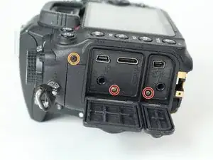
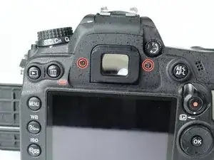
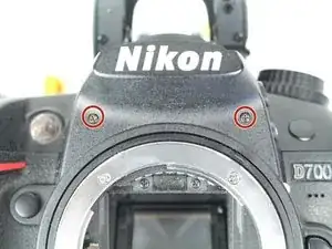
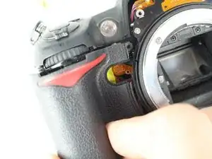
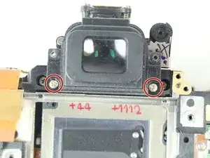
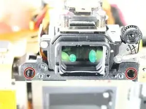
    • Remove the following screws from the port area:

    • Two 3.5 mm J000 screws.

    • One 6 mm J000 screw (right above ports).

    Note for D7100: the 2 screws marked red under the rubber covers are hidden below the middle cover. These screws are 3.8mm long. The orange screw is 6.35mm long.

    Olivier Biot -

  5. HkWQ6gc1GHGvddu4
    • Peel the rear rubber piece off with tweezers.

    This is not needed : if you don't touch this rubber & screw the SD card cover will come off at the same time that the back case.


    = Quicker and easier

    Xavier -

  6. 6XxLbBTXnoWYi1Ge
    • Remove one 4.25 mm J000 screw from behind the rear rubber piece.

    This is not needed : if you don't touch this rubber & screw the SD card cover will come off at the same time that the back case.


    = Quicker and easier

    Xavier -

    ⚠️ Note for D7100: this step IS needed when disassembling the D7100 body as the rubber conceals 2 JIS #000 screws (5.5 mm at top and 3 mm at bottom). Without removing those 2 screws the back case won't separate from the body. When detaching the rubber cover, make sure to keep the small plastic cover embedded at the bottom of the rubber.

    The SD card cover will fall out from the camera body when separating the back case.

    Olivier Biot -

  7. TEv5KiI1DkUae1PV
    • Pull the eyepiece cover up to remove it.

  8. kmD2nMN41RJFCpFK
    • Remove two 6 mm J000 screws from behind the eyepiece cover.

    • On D7100 models, there is an additional screw holding the back plate on. This screw is located in the diopter (dial with + - on it). This screw can be accessed by peeling up this sticker on the diopter.

    Concerning the diopter, it's wrong : D7000 also have a screw in it.


    See step 41.

    Xavier -

    Note for D7100: the 2 screws to the side of the eyepiece are 5.3mm long.

    Olivier Biot -

    Note for D7100: the screw holding the diopter dial is 11.4mm long.

    Olivier Biot -

  9. xDPUe1oxYB1bm3KO
    • Open the SD card cover by pushing slightly down with your thumb and sliding up.

  10. vLRVX4NIPSFASgd1
    • Remove four 6 mm J000 screws that secure the SD card cover.

    Note for D7100: these 4 screws are 6.30-6.35mm long

    Olivier Biot -

  11. nMT4dsBPdeK6J21C
    • Gently pull the SD card cover off.

    Attention! High voltage. After removing the memory card cover, remove the yellow sticker and use a 220 volt 15 watt incandescent lamp to discharge the capacitor.

    Rust Twentyone -

  12. EWyUIHjVmBVOgqYS
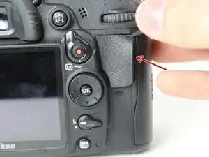
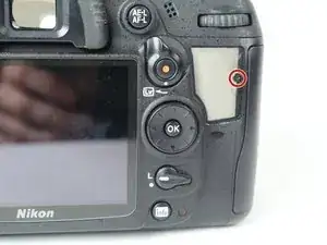
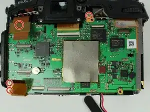
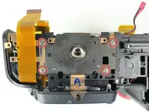
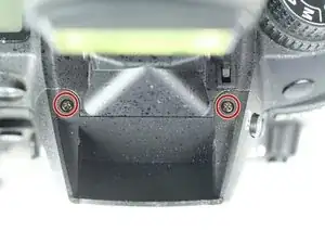
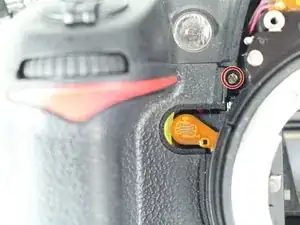
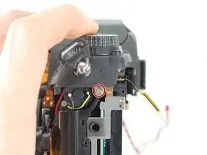
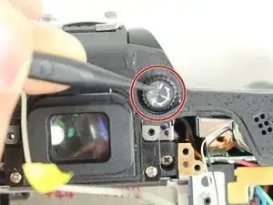
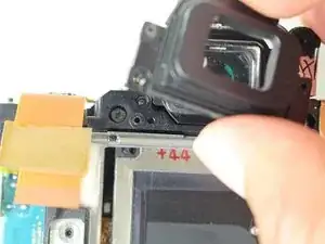
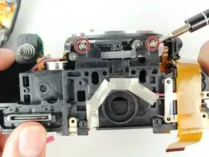
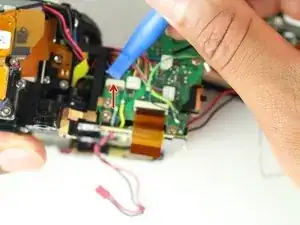
    • Remove the following screws that secure the back case:

    • One 6 mm J000 screw.

    • One 3 mm J000 screw.

    On D7100 both screws are the same length at 6mm

    Simon Tullett -

  13. pNJYwvZBCDlCCpZi
    • Carefully lift the back case off.

  14. lh3Oft4G2DQp6i2E
    lh3Oft4G2DQp6i2E
    FXEpWEbpTIw1UJYn
    aTqIKEtXXMoEpEf4
    • Disconnect the following two ribbon cables from the motherboard.

    • See our Cable Connector Guide for help with ribbon cable connectors!

    Note for D7100: the 2 ribbon cables that connect the back cover to the motherboard have ZIF sockets with the black lever at the bottom. Leave the other 2 (leftmost) ribbon cables at the bottom of the motherboard untouched.

    Olivier Biot -

  15. hiVpQMmmHvQwywQT
    hiVpQMmmHvQwywQT
    jaHEmXKNNr2MMIgV
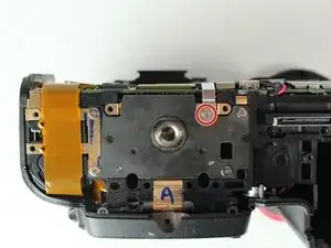
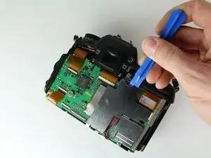
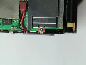
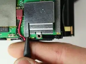
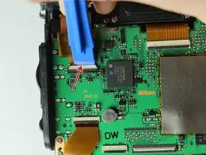
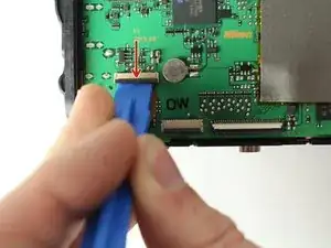
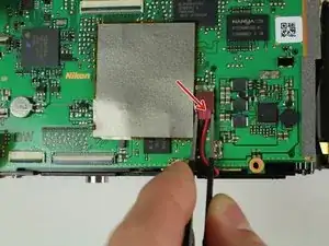
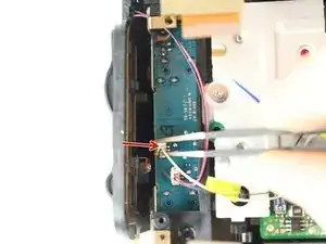
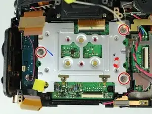
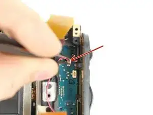
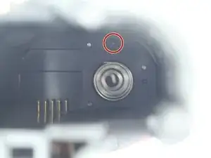
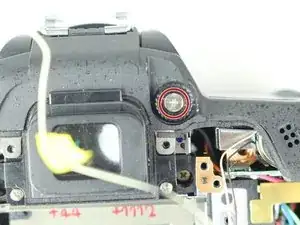
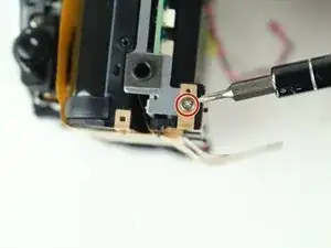
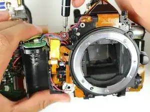
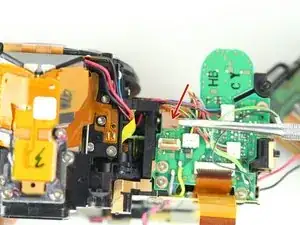
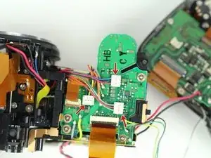
    • Remove the following screws securing the left motherboard shield:

    • One 2 mm J000 screw (on the bottom).

    • One 3.5 mm J000 screw (on the back).

    • Be careful of the grounding clips on the motherboard.

  16. fK2lsUZIQM6RHB4T
    • Gently pry and lift the left motherboard shield off.

    No need to remove shield. Risk of damaging clips holding shield.

    Ziyang -

    No Motherboard shield on D7100

    Simon Tullett -

  17. nTEWTNAKao3GrCri
    • Remove one 3.5 mm J000 screw securing the right motherboard shield.

    No need to remove shield. Risk of damaging clips holding shield.

    Ziyang -

  18. NNACDft5njSv6EL4
    • Gently lift the right motherboard shield off with the tip of a spudger.

  19. wgv453L4WEkbAppj
    wgv453L4WEkbAppj
    HBMtgXGXO32h4rxn
    uYtnEvYSojhopC2Q
    • Disconnect remaining ribbon cables.

    Note for D7100: at the top of the motherboard, there are 2 wide ZIF sockets (far left: white lever at top; far right: brown lever at bottom) and a narrow "no-fuss ribbon cable connector" (cable connector makes a 90° turn from 12 o' clock to 3 o'clock).

    Olivier Biot -

  20. vrKgmlOCkQZsnoSR
    vrKgmlOCkQZsnoSR
    tLGYNWDruWlMGiho
    • Disconnect remaining ribbon cables.

    One more ribbon behind press down tab

    Ziyang -

    Note for D7100: at the bottom of the motherboard, there are 3 ZIF sockets (far left, top: black lever at bottom; far left, bottom (underneath the previous): black lever at top; adjacent to the right: black lever at top).

    Olivier Biot -

  21. bPYkPsiLyFvMgpFg
    • Carefully disconnect the red connector with tweezers.

  22. 4Iurv4DleT5RAXaJ
    • Remove four 3.5 mm J000 screws securing the motherboard.

  23. FbPCIAVSAoAmHKEy
    • Gently pull the port side cover away from the motherboard.

  24. 5aopPFIduUGoVfRG
    • Lift the motherboard off.

  25. D6B3TYP6DEBnulQZ
    • Remove four 6 mm J000 screws securing the tripod plate.

    Only left 2 screw need to be removed. The tripod plate do not need to be removed.

    Ziyang -

    Actually, nothing needs to be removed !

    Skip this step and gain time and energy :)

    Xavier -

  26. ZQP4OJa5LfGHp4pC
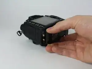
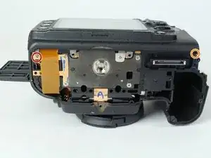
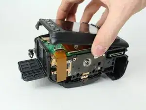
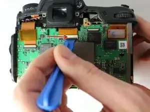
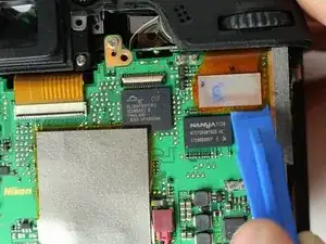
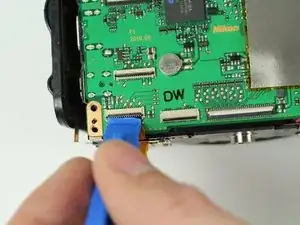
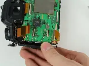
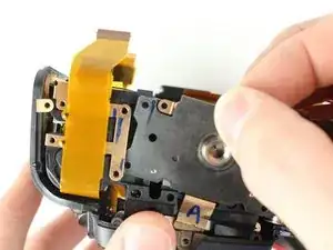
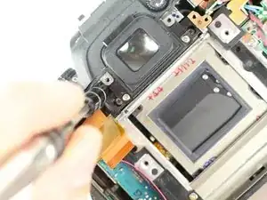
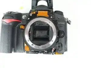
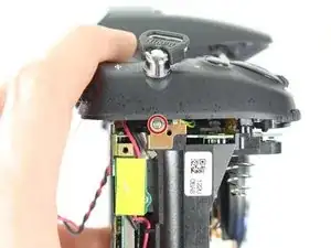
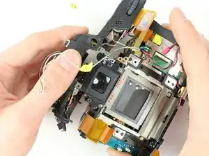
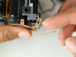
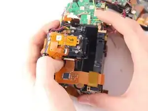
    • Carefully lift the tripod plate from the backside of the camera and slide out the grounding clip from under the lens mount.

    Skip this step (see comment step 25)

    Xavier -

  27. 5FKRWQep1XZ3Nwjh
    5FKRWQep1XZ3Nwjh
    CNdZsohxKqM6oHa1
    • Disconnect black and white speaker cable.

  28. jbauFMnUeKDTFGg4
    • Remove three 6 mm J000 screws securing the image sensor.

    Best to set markings on the three screws before removing sensor. To preserve alignment of sensor and body frame

    Ziyang -

    This step is NOT necessary if you don't plan on doing anything with the sensor itself

    -> just let it all attached together and save yourself time and energy

    Xavier -

    These 3 JIS #0 screws require quite some torque to unscrew.

    Don't forget to open the ZIF connector of the sensor ribbon cable before removing the sensor board.

    Olivier Biot -

  29. Sxw2GkHAtYlXvMYP
    • Carefully lift the image sensor plate out of the camera.

  30. XIVAkvWRPsHV4eDH
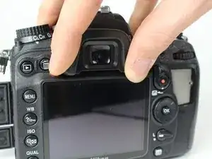
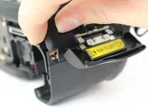
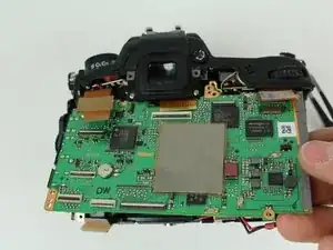
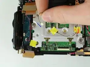
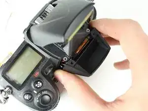
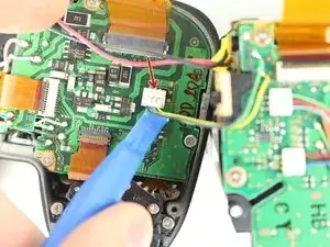
    • Manually pop up flash by inserting a screw driver to the left of the viewfinder and pressing on the metal lever.

    • It won't take much pressure. Press carefully and the flash will pop up when you find the right spot.

  31. NfoGRXLABjEmd2hU
    • Remove two 5 mm J000 screws from under the flash.

  32. rvtRkW6ZJblHwDhh
    • Remove two 3 mm J000 screws securing the front cover.

    These screws should be the other way around. I took the 5mm screws out of the front cover. 3mm screws from under the flash.

    Jamie MacLeod -

  33. ZBxhXVAG5HgE6O5K
    ZBxhXVAG5HgE6O5K
    jOfwj64QA2mCdGoH
    • Remove the front cover.

  34. XMXDXnZHfBFJmRFT
    • Carefully remove the port cover.

  35. m3RygWOOmGhXQRXP
    • Deroute the microphone cable.

  36. M6RkFcBqyiWPBb1S
    • Remove one 4 mm J000 screw from the front.

  37. dmDZNh2gD16k4ANS
    • Remove one 8.5 mm J000 screw from the battery compartment.

  38. YylGxGWgFI1yjBoH
    • Remove the grip carefully.

  39. qPdHvAgvHdKHJkao
    • Remove one 4 mm J000 screw securing the top case (under right strap hook).

  40. usd4GNyvuEKemhnD
    • Remove one 4 mm J000 screw securing the top case (under left strap hook).

  41. h6snmcabquK1ZcOW
    • Remove the sticker covering the diopter adjust screw.

  42. kVVIIoi6jhuj4CL6
    • Remove one 8.0 mm J000 screw.

    • Remove the Diopeter Adjust.

  43. 4EyB2AgZtnhqqZVq
    • Remove the top case.

    No mention of discharging the flash capacitor first?

    digimaan -

    Make sure you don’t get a shock off it .

    Dean Wilkinson -

  44. m3soBtMKuZmXSkNp
    • Remove the Black, Yellow, Green cable from the top case board.

    If intend to remove top panel entirely, will need to de-solder the black and red power cable

    Ziyang -

  45. DNlinKxNoqlPJAIV
    DNlinKxNoqlPJAIV
    YN14dQLLAbW63tps
    yOMEvyRQWRbu1MIh
    • Remove two 6.5 mm J000 screws securing the viewfinder.

    • Remove the viewfinder cover.

    Not necessary to remove the viewfinder cover for mirror box

    Ziyang -

  46. tAhICJ2HZYwGdMai
    • Remove one 3 mm J000 screw from the bottom left side of the camera.

    Don't do this : you don't need to, it's useless

    Xavier -

  47. Lb44InhXpTlgIJRm
    • Remove two 6 mm J000 screws from the left of the shutter.

    Not necessary

    Xavier -

  48. TKHQIORXHIBuQDyo
    • Remove two 6.5 mm J000 screws from beneath the lens mount.

  49. NZZ3TQsHSLdGcgRI
    • Remove two screws from just below and to the sides of the viewfinder.

  50. ORuaaMJaTDR133PL
    • Remove one 5 mm J000 screw from the top right of the camera.

  51. oCgIlBVJ3mxAOMUs
    • Carefully peel back ribbon cable on the bottom left of camera.

  52. 4NOBIgTvkJp1BsOD
    4NOBIgTvkJp1BsOD
    jl2ucREEQXGFDZsc
    • Remove the left front ribbon cable from top right of circuit board.

    The illustration indicates this connector to be tilted upwards. I did - and broke the female connector. As shown on the right hand picture, the same thing has happened during the dismantling forming the basis for this “ifixit” instruction.

    This ribbon should be pulled straight out - not lifted upwards

    Bored Nomore -

  53. xSJxuXBXHVJCRWrA
    • Remove all three wire connectors.

  54. fpvkdLL3OhsKaHjZ
    • Separate the shutter assembly from the camera body.

    This part left me in the lurch a bit, undid the top 2 screws holding the shutter in but there seemed more to undo to actually release the shutter.

    digimaan -

    If you intend to replace the shutter assembly only, you need to loosen it from the “shutter house” (don’ know correct term); (It is possible to purchase new blades only, but it seems complicated, and a shutter assembly costs around 35USD from Asia.)

    There are 3 screws; 2 visible on the “top” of the shutter assembly and one hidden underneath some ribbons on the “underside”. Study the new shutter to identify the screws being part of of the assembly and the ones holding it to the shutter house. (3 screws as mentioned)

    The power leads for the electric motor must be loosened by soldering (red and black cables).

    A ribbon with 4 tiny soldering points has to be loosened with a sharp tipped soldering iron; If you don’ t feel competent; bring it to someone who can do the very delicate soldering - especially for connecting the new shutter assembly.

    Bored Nomore -

    I have followed this guide. But 2 small bits of rubber have appeared. Not a clue from where. Any ideas?

    Paul Scott -

    When opening the shutter assembly, there are 3 small rubber parts. A larger one at the bottom left, 2 smaller ones fit in the bottom right. You'll notice rectangular slots (horizontal or at 45°). That's where they fit.

    Olivier Biot -

Conclusion

To reassemble your device, follow these instructions in reverse order.

Steven Castaneda

Member since: 02/04/15

691 Reputation

10 comments

Use a #00 Philips, not a #0, or you'll strip the screws. Also, there are two or three screws connecting the shutter assembly to the camera body, and its contacts are soldered on. So you need a soldering iron for the last step.

Michael Duncan -

im gonna be trying this soon , how long did it take and how difficult is it ,,,

Dean Wilkinson -

Guide not completed. Last step only shows removal of mirror box. Shutter assembly replacement not

Ziyang -

Regardless of possibly a few missing steps, this is a great lesson of how to deal with shutter replacement on my own. Hats off !!

Mateusz Witek -

How to reassemble diopter adjustment?

Jerome -

Can anyone help me with diopter control I took it apart by accident I don’t know how to put it back- jsarmd@yahoo.com

Jerome -

what model cmos battery

Mohamad Farid Ghazali -

Great that you posted link to Youtube video.

I had not been able to find the repair manual for this model and your step by step intructions helped me on the doubs I had.

Thanks.

Claudio Lupayante -

Done mine but I do confess I got help from a mate how repairs mobile phones and computers make sure you note where all the screws go wee kept them in order when removing them so you no where thy all go when re assembling it back together I don’t think I would try to do it myself wee did take some photos helped when rebuilding it back together it worked ok after maybe wee were lucky

George aitchison -

Where do I purchase internal parts for Nikon D series cameras? Thank you

Tony V -