Introduction
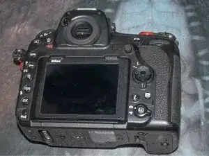
Here is a guide to help you replace the rear display cable on the Nikon D850.
There are many different screws of different lengths and thread types so a magnetic parts mat with a Vis-a-Vis marker is highly recommended to keep track of where they go.
-
-
Prepare an ESD safe work area. Remove the lens, battery, memory cards, and grip. Install a body cap to prevent dust from entering the body.
-
-
-
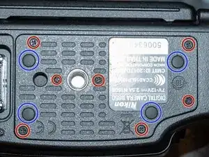
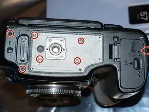
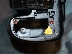
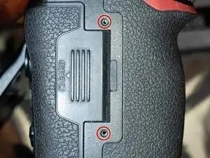
Remove the 7 J00 screws on the center bottom cover. The cover comes off easily
-
The 4 rubber feet usually stick to the camera body. There is no adhesive holding them to either part. Remove them and replace them in the bottom cover.
-
-
-
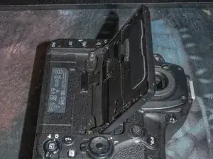
The rear case/display and card slot cover will come out at the same time. The rear case unfolds down, so watch those cables!
-
-
-
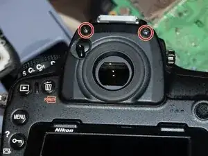
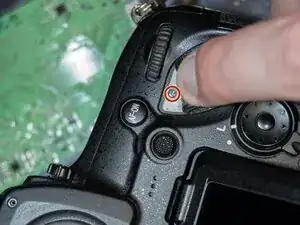
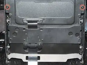
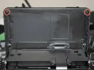
Flip the screen up, so the display is facing the viewfinder. Remove the 2 J00 screws at the top of the display
-
-
-
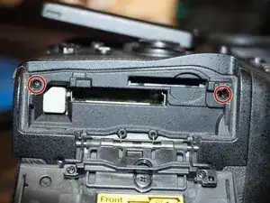
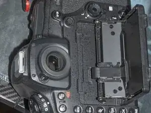
Flip the screen down towards the base of the camera and remove the bottom 2 J00 display screws.
-
-
-
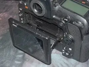
Move the display back parallel with the camera back, but away as far as possible. Support the back of the display so it doesn't fall apart before you're ready.
-
Slightly separate the display assembly from the frame by pulling straight back. Do not force movement if tension is felt from the cable.
-
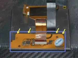
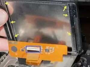
Once you have around 1cm of clearance between the display and frame, use 90%+ isopropyl alcohol and a thin, nonconductive pry tool to loosen the adhesive and separate the display cable marked in blue from the back bottom side of the display.
-
I found the area where the camera body cable attaches to the blue outlined area the easiest to get the solvent in and begin detaching the cable. Use caution as both the display cable and screen cable are quite fragile.
-
-
-
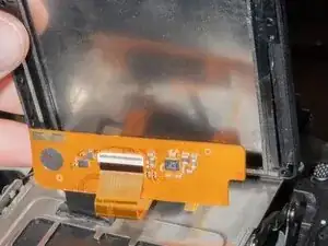
Once the cable is unglued from the back of the display module, the display can flip up towards the viewfinder and laid down face down on the back of the camera. Again, use care moving the display to avoid cable damage
-
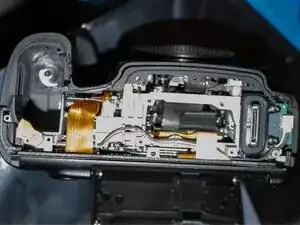
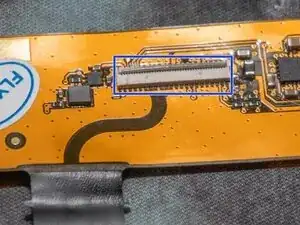
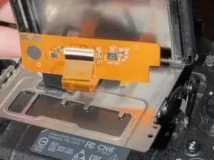
Support the back of the ZIF connector (in blue), to avoid flexing the cable and flip the latch opposite the display cable side up to allow the cable to release. Once the latch is released, the cable should pull out of the connector with almost no effort.
-
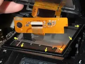
I've left the cables connected in this photo to aid reassembly order. There is a plastic midframe (yellow arrows) attached to the display assembly with the cables passing through it. Once the display cable is removed, the midframe may fall out. Set the display and midframe assembly aside.
-
-
-
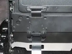
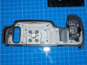
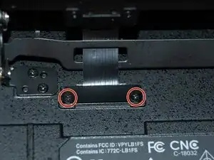
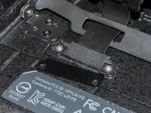
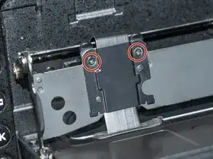
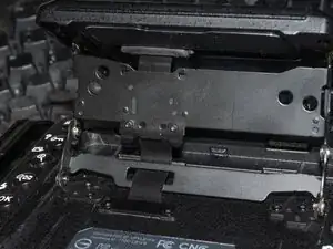
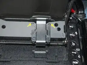
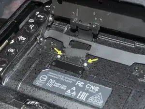
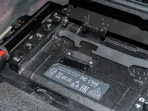
With the display removed from the rear body, remove the 4 screws on the cable retention mechanisms. The one on the flexible assembly is 2 pieces. The piece with the "ears" goes on the bottom with the ears out and up on reassembly.
-
-
-
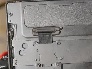
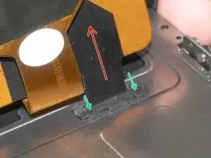
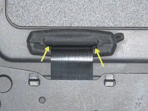
The cable will pull out from the body through the back (screen side) of the display frame. Use plastic tweezers or a spudger from the inside to push out the rubber cable guide (green arrows) from the rear of the display frame.
-
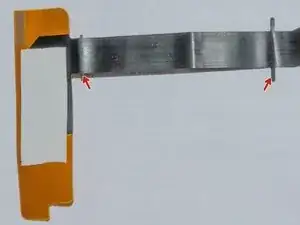
Once the rubber cable guide is removed, gently guide the cable around the frame and out of the camera body. The cable has positioning ears on it (red arrows) that can catch and snag on the way out of the body, so use care!
-
-
-
From the back side of the display frame, route the cable from the display over the top bar, then through the hole on the bottom bar, and finally through the passthrough on the camera back cover. Do not install any of the cable retention brackets/grommets/covers at this point.
-
-
-
With the cable from the display coming from the top, and the midframe installed, route the cable as shown. Make sure the release lever on the connector is flipped up and insert the display cable. It should go in and seat with little effort.
-
While making sure the display cable remains seated fully in the connector, support the back of the display cable and press the connector latch down to secure the cable.
-
Once the connector is closed, reinstall the rear display, making sure not to crease or pull on any cables. Feed as much of the black part of the display cable through the back of the rear frame as possible. While holding the display together, flip it all the way up to reinstall the bottom screws, and all the way down to reinstall the bottom screws.
-
Once the display is installed, inspect the rear of the display and make sure the cable is still coming out straight, isn't kinked anywhere, and is routed properly through the holes and frame components.
-
-
-
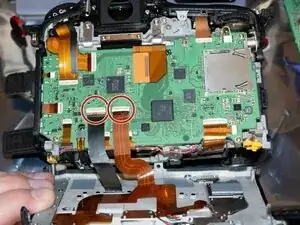
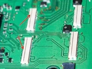
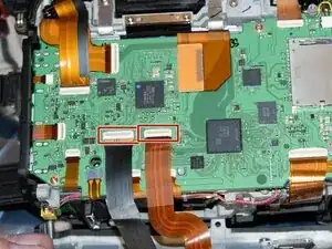
Make sure the release levers on these connectors are flipped up, then gently reinstall the new display cable and control cable to the main board, then push the levers down.
-
Install the card reader cover at the same time as the rear cover.
-
At this point reassembly of the camera body is the reverse of removal. Reinstall all rear cover and bottom cover screws but do not install any cable retention yet.
-
-
-
Insert the split grommet into the back of the display frame. A set of blunt tweezers or pointy plastic spudger helps get the grommet fully seated. Use care to avoid poking the cable.
-
Make sure the smaller "ears" of this cable are at the grommet passthrough, to ensure enough length for cable movement.
-
-
-
Install the mid-frame cable guide with the display flipped toward the bottom of the camera. The cable should be able to slide freely through this guide.
-
Make sure the little ears on the display side of the guide are clipped into the frame before screwing the bottom plate on. These are tiny screws and do not take being overtightened well. Snug is perfect for these.
-
-
-
The cable section that enters the camera body has ears that sit in these grooves. Push excess cable into the body, set the cable in these grooves, place the rubber piece over it and screw on the cover plate while preventing movement. This will position the cable appropriately in the frame to avoid kinks and excessive tension on the cable.
-
-
-
Remove the body cap, install a lens, memory cards and other accessories. Power on the camera and verify the screen and all back panel buttons function normally. Make sure the display can articulate fully without any cable tension or snagging.
-


To reassemble your device, follow these instructions in reverse order.