Introduction
This guide has been updated by iFixit staff! Read the new, official guide here.
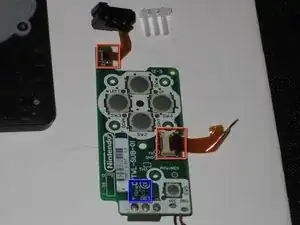
The battery contacts, power button and D-pad are on their own separate PCB inside the DSi; the PCB connects to the status LEDs using a ribbon cable and to the main board using a ribbon cable and power cable.
If you are replacing the bottom DSi case (e.g. to add an aftermarket translucent case), you will need to remove this board and put it in your new case.
If you blow the fuse (usually by plugging the battery in backwards), the orange charging LED will flash when plugged into A/C power, and the unit will refuse to power on; this guide will show you how to replace the board or even to repair the blown fuse on the board.
-
-
L Button.
-
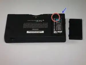
Top of the battery pack.
-
To remove the battery pack, place your fingernail or a spudger at the top of the battery near the L button. Gently lift the battery out.
-
-
-
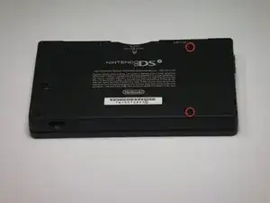
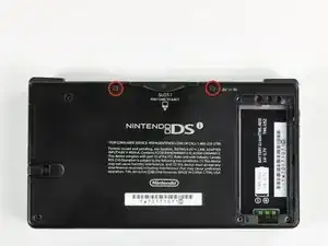
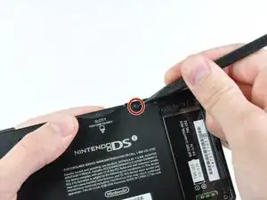
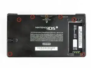
Two screws are hidden underneath two rubber feet highlighted in red.
-
Use the tip of a spudger to pry the rubber feet out of the lower case.
-
-
-
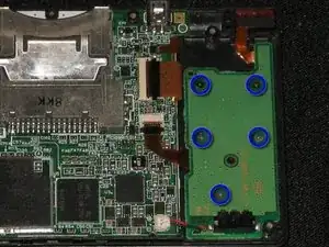
Remove the following screws securing the lower case to the body of the DSi:
-
Six 5.2 mm Phillips #00 screws.
-
One 2.7 mm Phillips #00 screw.
-
-
-
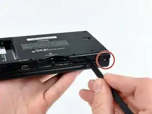
Insert the spudger in between the lower casing and lower panel near the top right corner of the DSi.
-
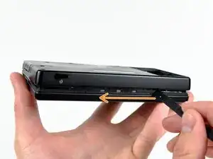
Carefully run the spudger along the edge of the outer casing, creating an opening between the body and the casing.
-
Continue running the spudger around the body of the DSi until the majority of the lower case has been separated.
-
-
-
Carefully lift the lower casing from its bottom edge.
-
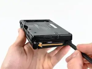
Pry the volume and SD board cable up from its socket on the motherboard using a spudger.
-
Once the cable is completely removed, then you may take off the entire outer casing.
-
-
-
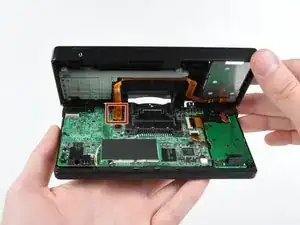
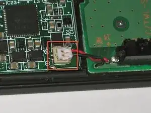
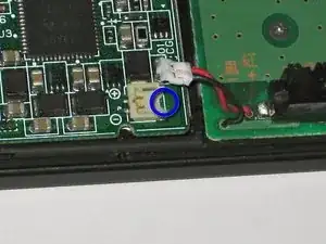
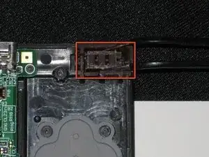
The connector is two pieces -- a white "male" piece (connected to the wires), and a beige "female" part (soldered to the main board).
-
There is a small "notch" in the female part, to give you a place to insert a small flat-head screwdriver. Put the corner of your screwdriver in there, and twist it gently to push the white part up (away from the main board). Do not try to pull it to the right (towards the battery board).
-
-
-
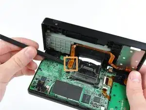
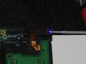
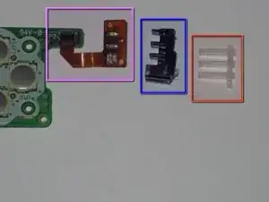
Insert a 1.5mm flat-head screwdriver into the notch to the right of the LED assembly, and pry the black plastic frame out of the case.
-
Using some tweezers to pull out the clear plastic light pipe assembly.
-
The orange flex cable (with the LEDs) is attached to the black plastic frame with adhesive; if you accidentally pull the cable off the plastic frame, pull the plastic frame and light pipe out with tweezers and reassemble them.
-
-
-
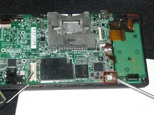
Remove the battery board and LED assembly, and flip them over.
-
If either of the two flex ribbon cables have been disconnected or damaged, use a spudger to flip the black latch up (away from the board), remove the cable, reinsert it, and press the latch down.
-
If your console does not power on, use an ohmmeter/continuity checker to test the SMT fuse F1. It should read as 0 ohms (short circuit). If not, you will need to replace the fuse or replace the board.
-
If you are stopping here, follow these instructions in reverse order to reassemble your device.
-


To reassemble your device, follow these instructions in reverse order.
One comment
When i changed my housing and reassembling, the DSi won’t turn on
trace back the problems and it ended up in this battery board (i change it with another battery board and it was okay)
my question is: what prevents my DSi from turning on? i checked all the ribbon cables and the battery cable below and everything was fine
i need it for my 2nd DSi, thanks in advance