
Introduction
The motherboard of the Panasonic PV-GS9 can fail over time, resulting in difficulties such as the device not turning on or poor image quality. This article will show you how to safely remove and replace the defective motherboard. Follow each step carefully to ensure a smooth and error-free process. To provide clarity during the replacement, keep your equipment and components organized.
Before You Start:
- Set up a flat, clean workspace: Work on a stable surface to avoid accidents or the loss of minor parts.
- Turn off your device and disconnect from the charger.
-
-
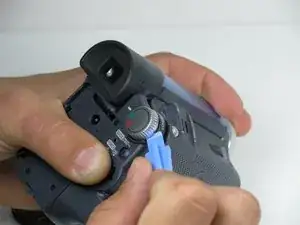
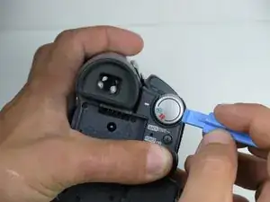
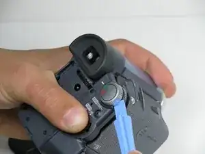
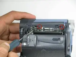
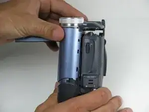
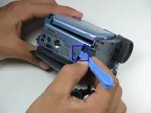
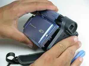
Locate the blue plastic tool opener, then remove both the round record/playback and record/power control knobs by prying it open from the camcorder.
-
-
-
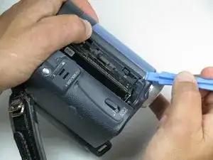
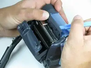
Open the tape compartment.
-
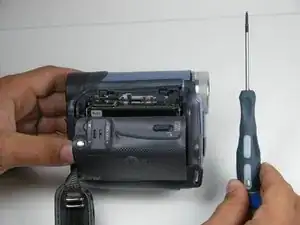
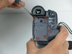
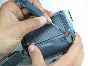
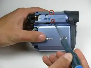
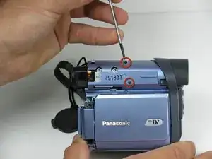
Flip over the camcorder and find the two 4.5mm screws, which are approximately 2 inches apart.
-
Using a #00 Phillips screwdriver, remove the screws
-
-
-
Use a plastic prying tool, remove the gray trim piece by opening and gently prying it off from top of the camcorder.
-
-
-
Rotate the camcorder so that the camera lens is facing you.
-
Remove the four black 4.5mm screws, sitting behind the battery.
-
Remove the 5th screw to the right of the battery dock.
-
Remove the battery by gently pulling away from the camcorder.
-
-
-
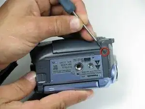
Rotate the camcorder so that the tape compartment is facing you.
-
Remove the single 4.5mm black screw above the hook for the hand strap.
-
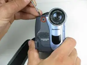
Rotate the camcorder so that the lens is facing you.
-
Remove the single 4.5mm black screw from the front panel.
-
-
-
Rotate the camcorder so that the bottom is facing towards you.
-
Remove the single remaining 4.5mm black screw from the bottom.
-
Remove the four silver 4.5mm screws from the body.
-
-
-
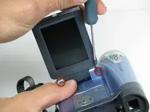
Open the LCD screen on the side of the camcorder.
-
Using a #00 screwdriver, remove the two 4.5mm silver screws located on either side of the hinge of the LCD screen.
-
-
-
This should come apart with relative ease; however, a plastic pryer tool may help remove the panel if it is struggling to come apart.
-
-
-
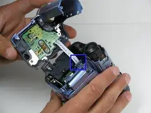
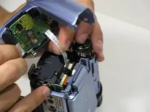
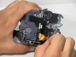
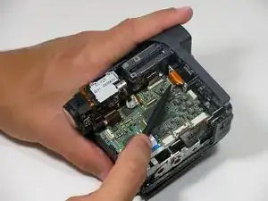
Using your fingers, carefully pull the ribbon cable away from the logic board to disconnect it.
-
-
-
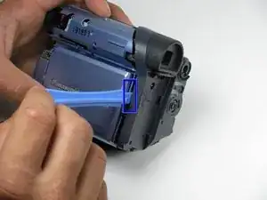
Place a plastic opening tool under the bottom of the blue panel beneath the camcorder.
-
Move the plastic opening tool up the side of the camcorder as shown. Carefully separate the LCD panel from the rest of the camcorder.
-
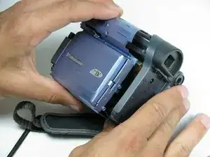
Remove the panel from the camcorder.
-
-
-
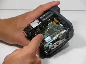
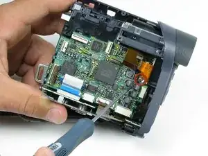
To remove the logic board from the body, use the #00 phillips head screwdriver and remove the 4mm silver screw from right side of the board.
-
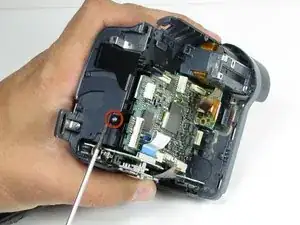
Next, rotate the camcorder so the front is facing you and remove the 4mm silver screw from the front panel.
-
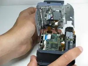
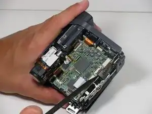
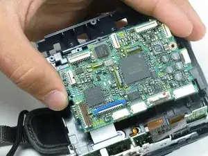
Carefully lift the logic board away from the camcorder.
-


To reassemble your device, follow these instructions in reverse order.