Introduction
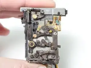
The rubber dampers that cause slow or stuck mirrors are located in the mirror box mechanism. Fully disassembling the mirror box, cleaning problem areas, and installing new dampers is necessary to fully address the issue. The following guide details the disassembly process and how to get replacement dampers. It also recommends other general cleaning and maintenance to improve the performance of the mirror box mechanism.
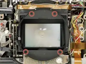
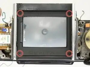
Removing the flex PCB from the mirror box is recommended when servicing the mechanisms as it will reduce the risk of damaging the electronic components. Removing the focusing screen is also recommended.
Any disassembly of the LX body will compromise the weather sealing. New seals must be reapplied during final reassembly to restore weather proofing.
-
-
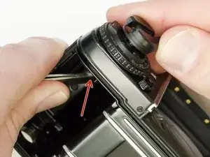
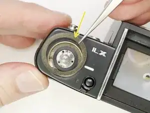
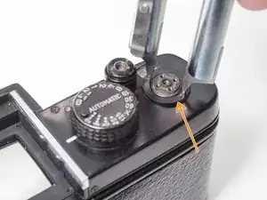
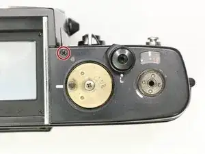
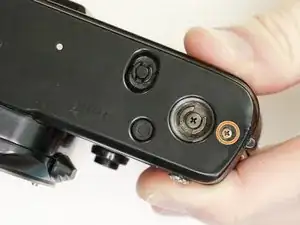
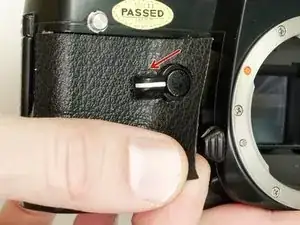
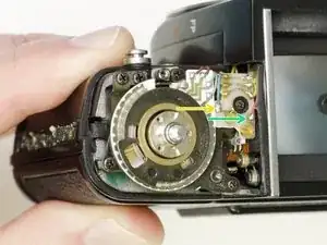
Place a thin tool in the rewind fork and unscrew the topside knob.
-
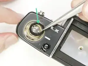
Remove the washer under the rewind knob.
-
-
-
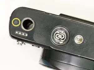
Remove three #000 5.5 mm screws.
-
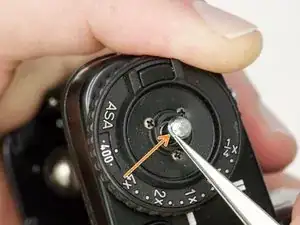
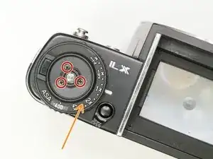
Remove exposure compensation dial assembly.
-
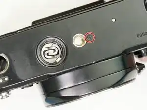
Remove washer.
-
Remove rubber seal.
-
-
-
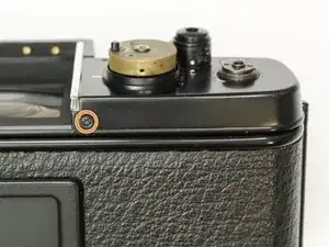
Use a piece of tape wrapped sticky side out to grip the winding lever cover. Turn clockwise to loosen and remove
-
Remove four #000 2.5 mm screws.
-
Use spanners to remove top cover retaining nut.
-
-
-
Gently remove the rubber covering around the shutter speed dial.
-
Remove three #000 1.6 mm screws.
-
Remove cover ring.
-
-
-
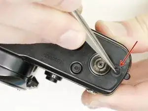
Remove the rubber bumper covering the screw.
-
Remove one #00 1.8 mm screw.
-
Repeat on the other side of the bottom plate (#00 3.0 mm screw).
-
-
-
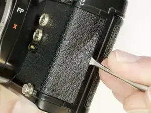
Use isopropyl alcohol to soften the adhesive along the edge of the leatherette.
-
Use a dull spudger or scraper to peel off the covering.
-
Turn the self timer lever to the 9 o'clock position.
-
Loosen the entire right side leatherette in the same manner, then work it over and around the self timer lever to remove.
-
-
-
Remove the two cover plates under the leatherette.
-
They may stick to the covering adhesive and come off on their own.
-
This small plug may also be loose.
-
-
-
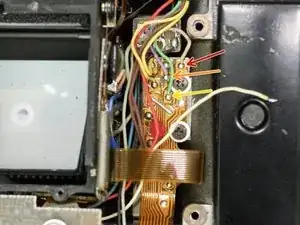
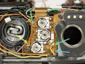
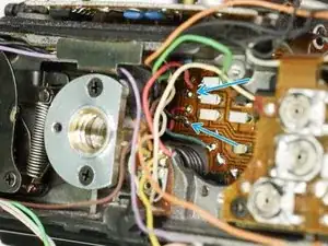
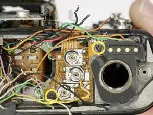
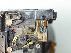
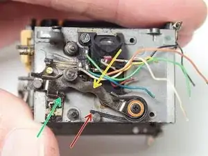
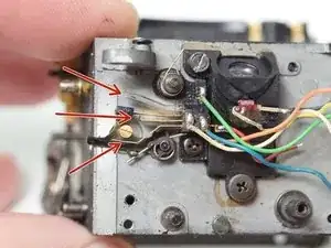
Unsolder one gray wire.
-
Unsolder two yellow wires.
-
Unsolder one blue wire.
-
Unsolder one red wire.
-
-
-
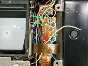
Unscrew four #00 X mm screws.
-
Unsolder one white wire.
-
Unsolder one pink wire.
-
Unsolder one light green wire.
-
Check the mounting points for shim washers. If they are loose, note the position and remove.
-
-
-
Unsolder one pink wire.
-
Unsolder one purple wire.
-
Unsolder one green wire.
-
Unsolder two yellow wires.
-
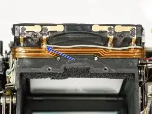
Unsolder two brown wires under the loop of flex cable.
-
Unsolder one gray wire.
-
-
-
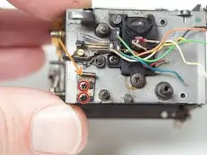
Unscrew three #00 3.0 mm screws.
-
Remove exp/ISO resistor assembly.
-
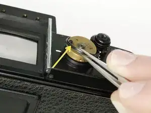
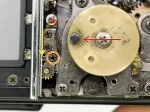
Remove exp. compensation coupling cam.
-
There are two loose ball bearings that sit in these holes. Do not lose.
-
Installation Note: Push this lever back to properly seat the exposure compensation lock. Check that the flag in the viewfinder is working properly. It should not be visible when dial is set to 1x and pop into view when set to any other value.
-
-
-
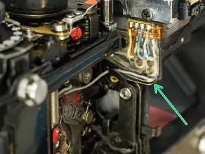
Unsolder five black wires.
-
Unsolder two green wires.
-
Unsolder one purple wire.
-
Unsolder one yellow wire.
-
Unsolder one orange wire.
-
Unsolder one light brown wire.
-
-
-
Unsolder one light blue wire (may appear beige).
-
Unsolder one green wire.
-
Unsolder one pink wire.
-
Unsolder one blue wire.
-
Unsolder two black wires.
-
Unsolder one brown wire.
-
-
-
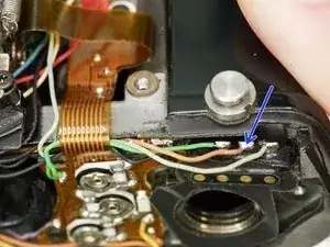
Unsolder one yellow wire.
-
Unsolder one white wire.
-
Unsolder one light blue/teal wire.
-
Unsolder one gray wire.
-
-
-
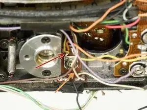
Turn shutter speed selector to 'Auto'.
-
Turn lock lever screw clockwise to loosen. Do not remove.
-
Push lock lever toward the needle indicator gear.
-
Turn lock lever screw counter-clockwise to tighten.
-
-
-
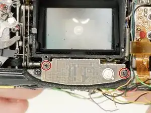
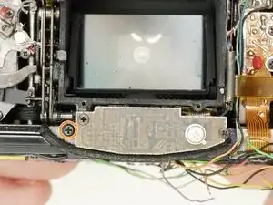
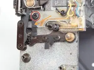
Remove two #00 2.8 mm screws. Remove two loose spacers underneath the PCB.
-
Remove two #00 2.0 mm screws.
-
Remove two #00 2.0 mm screws.
-
-
-
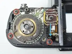
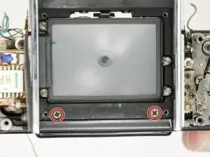
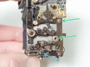
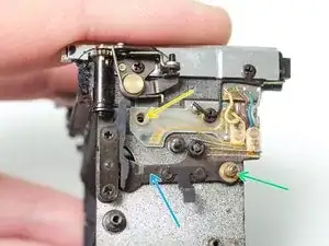
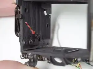
Remove two #00 3.0 mm screws.
-
Remove one #00 5.0 mm screw.
-
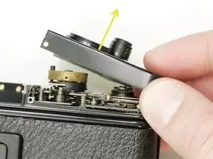
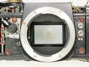
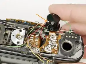
Remove mirror box by lifting up then out. Pull slowly and check for snags as you remove.
-
-
-
Before installing the mirror box, the shutter should be wound and the mirror released into the taking position (up against the focusing screen).
-
After mounting the mirror box, make sure all necessary wires are available through the bottom of the camera for soldering.
-
Check for proper coupling of the self timer and the shutter button release.
-
Check that the closing curtain latch sits forward of the mirror return latch.
-
Check that the FP switch lever holds the magnet lever.
-
Select one of the mechanical shutter speeds and test the function of the mirror and shutter. The camera should be capable of a complete exposure cycle at this point.
-
-
-
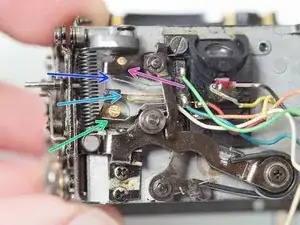
SW g1: On when mirror is down. Off when mirror is up. Yellow to ground.
-
SW g2: Off when mirror is down. On when mirror is up. Blue to brown.
-
SW T: Off when mirror is down. On when mirror is up. Gray to top contact.
-
SW MDT: Off normally. On when shutter button is half pressed or when mirror is up. Orange to ground.
-
SW P: Off normally. On when shutter button is half pressed or when mirror is up. Red to blue.
-
SW FP: Off when mirror is down. On when mirror is up. White to ground.
-
SW MDS: Off when mirror is down. On when mirror is up. Green to ground.
-
-
-
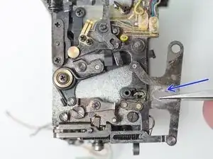
This video shows a properly functioning mirror box mechanism for reference.
-
The release latch should move freely when the mechanism is not charged.
-
SW P, on the bottom of the mirror box, should close before the mirror is released.
-
Charge the mechanism by pulling the mirror return lever towards the back of the camera.
-
Push the mirror release lever down to flip the mirror up.
-
Pull the mirror return latch to flip the mirror down.
-
-
-
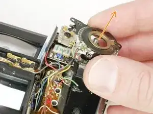
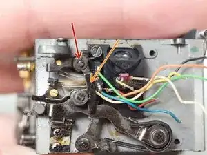
Remove one 1.9 mm #000 screw.
-
Use a u-bit driver to remove one nut.
-
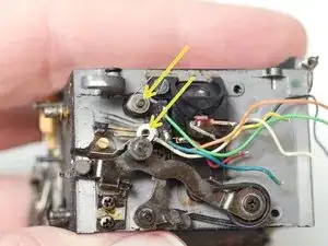
Remove retainer plate.
-
Remove two shim washers.
-
Remove one 1.5 mm circlip and shim washer.
-
Remove aperture priority actuating lever.
-
-
-
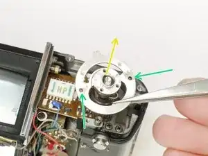
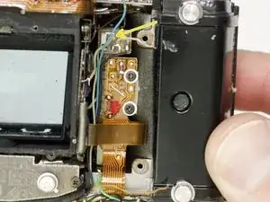
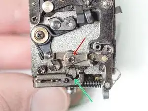
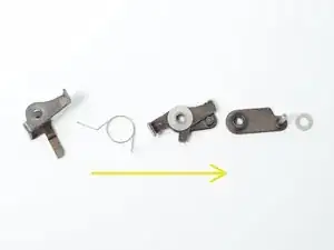
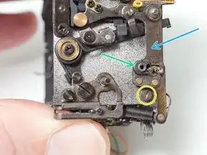
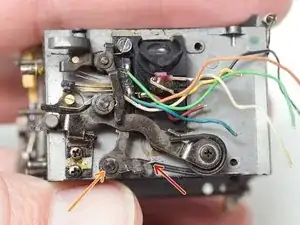
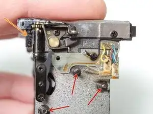
Remove one 1.5 mm circlip and shim washer.
-
Remove mirror release latch assembly.
-
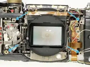
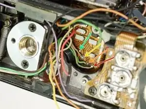
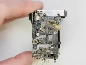
The third image shows the stack up of components in the assembly, bottom to top. This can be quite difficult to get back together properly. It may be easier to reinstall it on the post piece by piece, rather than to install as a complete assembly.
-
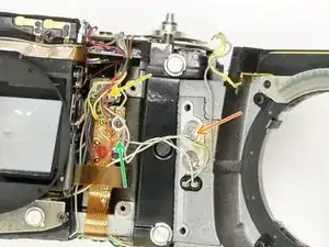
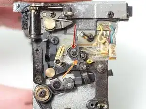
Installation Notes: Make sure this arm of the latch sits to the right of the power switch lever. This is the mechanism that turns on the light meter when the shutter button is half-pressed. Also pay attention to the attachment points of the bias spring.
-
-
-
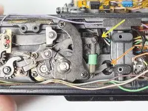
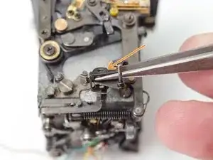
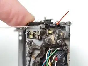
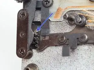
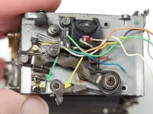
Unhook one end of the mirror flip-up spring. A piece of string or fishing line can be helpful.
-
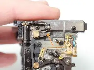
Unhook the brake lever spring.
-
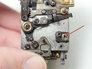
Remove one 3.0 mm flat head shoulder screw.
-
Remove one retaining ring. Circlip pliers are required.
-
Remove mirror actuating lever.
-
-
-
Remove one 3.4 mm #00 screw and shim washers.
-
Unhook bias spring.
-
Remove aperture actuating lever.
-
-
-
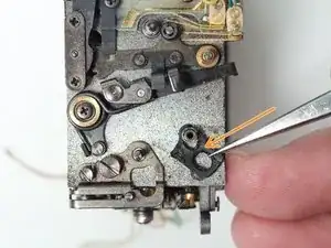
Remove one 3.8 mm #00 screw.
-
Remove retaining clip.
-
Remove spacer.
-
Remove brass sleeve.
-
Remove mirror flip-up lever.
-
Installation Notes: This lever is connected to the mirror seat with a geared interface. The exact position of the gear mesh needs to be replicated during reassembly, otherwise the mirror will not move through its full travel.
-
-
-
Remove one 4.2 mm flat head screw.
-
Remove one 4.1 mm flat head screw.
-
Installation Notes: When reassembled with new stop plate dampers, there should be a small gap between the tip of the mirror return lever and the end of the guide plate slot.
-
-
-
Unhook bias spring.
-
Remove one 1.5 mm circlip.
-
Swing lever out and lift off post.
-
Remove bias spring.
-
-
-
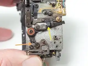
Use pliers to unhook the mirror return spring from the post.
-
Remove one 3.3 mm #00 screw.
-
Lift off the mirror return lever.
-
The mirror return lever has an old rubber damping pad on it that should be cleaned off and replaced.
-
-
-
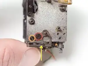
Remove two 2.4 mm #00 screws.
-
On some LX models, the mirror return stop will also have a rubber damper here.
-
-
-
Thoroughly clean all removed parts with isopropyl alcohol.
-
Clean all posts and pivots on the mirror box.
-
Remove and replace all foam seals with new material.
-
-
-
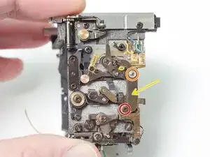
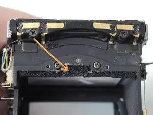
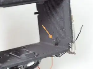
Remove the rubber damper from the mirror rest seat.
-
Remove second mirror rest. This is a rubber cap placed over a metal stud.
-


Further disassembly of the mirror box is possible but this is enough to remedy most issues. Reassemble in reverse order and check functionality along the way.