Introduction
The shutter speed resistor is a common point of failure in the Pentax LX. The component consists of a pair of feeler contacts sliding along a carbon filament. The resistance value created by this assembly communicates the selected shutter speed to the camera. Over time the contacts can become oxidized and/or dirty resulting in erratic behavior when using the manual electronic shutter speeds. Cleaning the resistor can restore the camera to normal functionality.
Any disassembly of the LX body will compromise the weather sealing. New seals must be reapplied during final reassembly to restore weather proofing.
Tools
-
-
Use a piece of tape wrapped sticky side out to grip the winding lever cover. Turn clockwise to loosen and remove
-
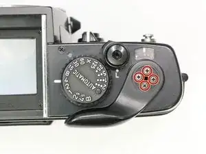
Remove four #000 2.5 mm screws.
-
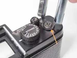
Use spanners to remove top cover retaining nut.
-
-
-
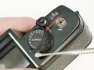
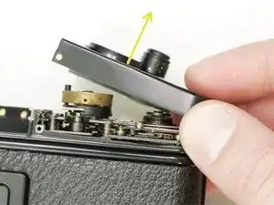
Gently remove the rubber covering around the shutter speed dial.
-
Remove three #000 1.6 mm screws.
-
Remove cover ring.
-
-
-
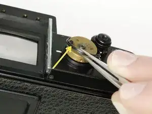
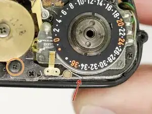
Unhook lever spring.
-
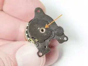
Remove slotted nut. Use isopropyl alcohol to soften thread lock if necessary.
-
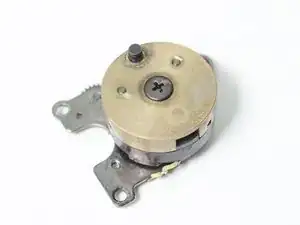
Remove all components of the timing switch assembly.
-
-
-
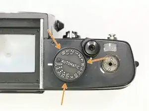
Turn shutter speed selector to 'Auto'.
-
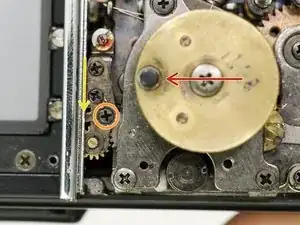
Turn lock lever screw clockwise to loosen. Do not remove.
-
Push lock lever toward the needle indicator gear.
-
Turn lock lever screw counter-clockwise to tighten.
-
-
-
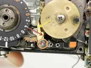
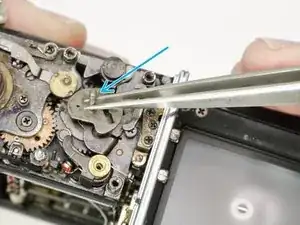
Unsolder two yellow wires.
-
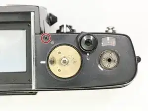
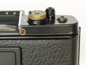
Remove one #00 4.0 mm screw.
-
Remove one #00 2.2 mm screw.
-
Remove one #00 2.5 mm screw.
-
Remove high speed cam.
-
-
-
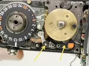
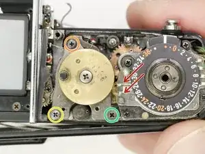
Rotate the speed dial until the feeler contacts are visible in the gap.
-
Spray with a plastic safe contact cleaner and rotate back and forth.
-
Check the resistor values at the slow speed settings. They should range from around 9 kΩ (at 60) to 200 kΩ (at 4s) with no dead spots.
-
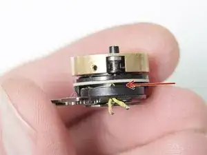
Clean the seat for the high speed cam with isopropyl alcohol. A narrow cotton bud or a floss pick work well.
-
Lubricate the high speed cam seat with shutter oil.
-


To reassemble your device, follow these instructions in reverse order.