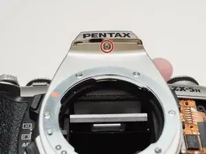
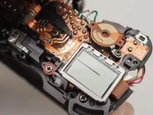
Introduction

How to remove the two flash capacitors and the PCB they are attached to. A donor part from another camera will be needed.

  1. lgs2BFmwctNUvEEY
    • Push down on the screw to depress the spring loaded hinge and release the door.

  2. xqMOa4QfTrEMSjLQ
    • Remove six 5.3 mm #00 screws.

    • Remove one 3.4 mm #00 screw.

    • The short screw has a machine thread and screws into the plate underneath. The rest screw into the plastic body.

  3. JBNm1gvrrVIsOnvC
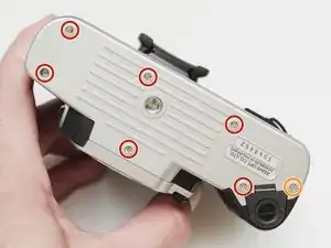
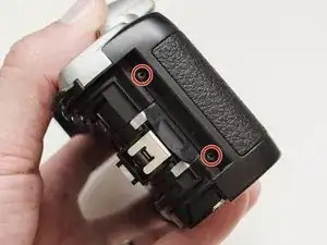
    • Remove three 5.3 mm #00 screws (the bottom-most screw is not always present).

    • Remove one 7.3 mm #00 screw.

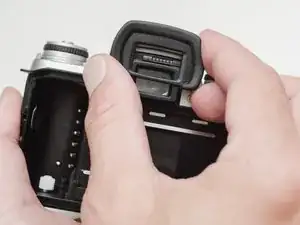
    • Remove the remote trigger cover.

  4. kaurbKcGc3sICMvp
    kaurbKcGc3sICMvp
    qAMWaUYPEdKSqKBQ
    • Remove one 3.4 mm #00 screw.

    • Remove two 5.3 mm #00 screw.

    • Gently lift up on the flash housing to help remove the cover if necessary.

  5. XTT2gETZspMWvdLW
    • Remove two 3.9 mm #00 screws.

  6. ARa5irnNBe4saLjG
    • Slide the eye cup up and off to access the screws underneath.

  7. WXSxikGQnRIdBm53
    WXSxikGQnRIdBm53
    dYUQ2h3O4Uup2OHy
    ScUMgBowkxHStFqJ
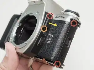
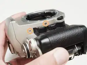
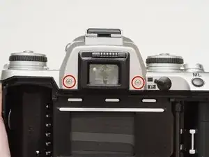
    • Remove two 5.3 mm #00 screws by the eyepiece.

    • Remove one 6.8 mm #00 screw in the battery compartment.

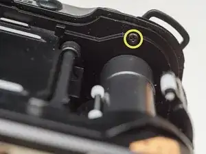
    • Remove one 7.0 mm #00 screw near the take up spool.

  8. 1w4wgSUjvi2VyATp
    • Lift the cover so it is just free of the body. It is still attached by several wires.

  9. UYOb45jluXTBh2EH
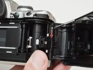
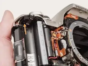
    • Use a 1kΩ-10kΩ resistor to discharge the capacitor. Place the resistor between the blue wire, exposed in the previous step, and ground.

    • The flash capacitors store energy at a very high voltage. Failing to discharge the capacitors properly could result in personal injury and/or damage to the camera.

  10. aldFfVMXX1eCBqkS
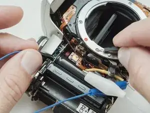
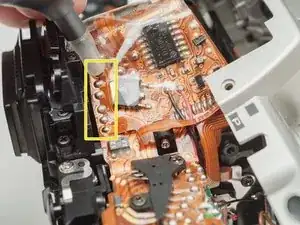
    • Unsolder one green wire.

    • Unsolder one blue wire.

    • Unsolder one brown wire.

    • Unsolder one black wire.

  11. 3ePHgPVX2WpknD6R
    3ePHgPVX2WpknD6R
    6ygxoCAYVRGEJBiX
    fnEtfvDRFEDU16AV
    • Unsolder one black wire.

    • Pull black wire out from its routed location.

    • Unsolder flex connector

    • Be careful not to overheat the flex circuit. Work in short durations. Allow for cool downs in between if necessary.

    • Some repairs can be performed with the top cover still connected but the flex connection is fragile and easily damaged.

  12. CegHUtL3thGVHOMR
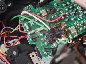
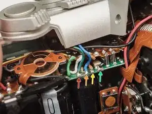
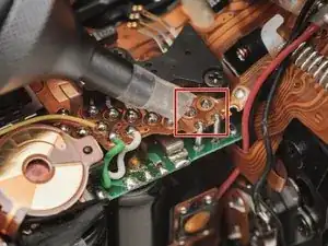
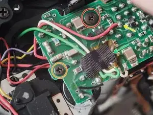
    • De-solder the indicated joints. Use a solder sucker on the tabbed connections.

    • Pull the black wire from the battery flex to get more slack in the connection to the top cover.

    • Be careful not to overheat the flex circuit. Work in short durations. Allow for cool downs in between if necessary.

  13. ywWMNUNRinvtxUBv
    • Use a solder sucker to de-solder the four posts from the flex circuit.

    • This is the most difficult part of the repair. Patience and persistence are required.

    • Be careful not to overheat the flex circuit. Work in short durations. Allow for cool downs in between if necessary.

    A small remark. Having tried to use a "regular good" solder sucker to remove solder, it sucked in the pin connecting the two flexible boards along with the solder. Apparently, I heated the soldering spot too well. The remaining solder was successfully removed with the Goot CP-2015 wick.

    Stepan Koloskov -

    It is very easy to reflow the solder on the green PCB and knock the pins out of position. They are very conductive. But I haven't sucked one up yet, haha. Solder wick is good solution.

    Sam Gustafson -

  14. PQH4ClkgMQYxYmRP
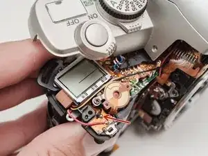
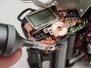
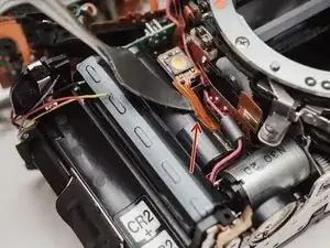
    • Unsolder film advance motor connections.

    • Unsolder sprocket counter connections.

    • Unsolder power and ground connections.

    • Unsolder panorama switch connections.

    • Be careful not to overheat the flex circuit. Work in short durations. Allow for cool downs in between if necessary.

  15. N2ZakjMEIJ4uPcEx
    • Remove one 4.3 mm #00 screw.

  16. BJWKBkWKOX3LNEXa
    BJWKBkWKOX3LNEXa
    iUKQN4JxkMihbEHH
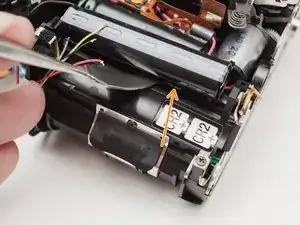
    • Gently pry up the plastic carrier under the flex circuit. It may catch slightly on the battery contact tab.

    • Pay close attention to the connections around the four through-hole posts as you lift the flex. Make sure that no solder is left over and that it pulls away freely.

    • This metal tab is lightly held in place with lacquer and can easily come loose. Keep an eye on it.

  17. rW36Nytm5MX4ypxw
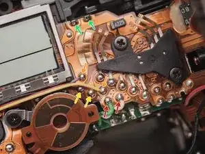
    • Remove one 3.3mm #00 screw.

    • Remove one 3.9 #00 screw.

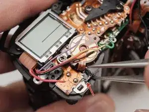
    • De-solder the red wire.

    • Peel off the black tape. Leave it attached to the wires.

  18. RW4tpsArJ2gxXCJF
    RW4tpsArJ2gxXCJF
    ZVd5QUYQqYSrQWBb
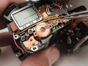
    • Gently peel the flex circuit from the surface of the capacitor.

    • There may be additional adhesive underneath the larger capacitor.

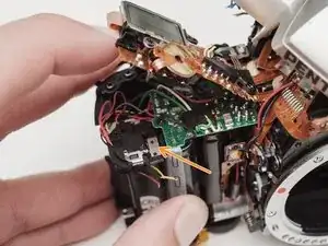
    • Lift the two capacitors and the flash PCB out as a single unit.

    • The double sided tape used to secure the capacitors can be softened with isopropyl alcohol if necessary.

Conclusion

To reassemble your device, follow these instructions in reverse order.

Sam Gustafson

Member since: 02/09/22

7682 Reputation

0 comments