Introduction
This is a guide on how to replace the speakers on a Philips DS3000/37 Audio Dock. Because this repair requires soldering, the soldering technique page linked here might be helpful. How To Solder and Desolder Connections
-
-
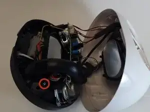
Insert an opening tool between the gray front casing and white back casing.
-
Pry the gray casing away from the white casing.
-
-
-
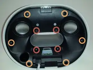
Position the white casing so that the black internal housing is facing upwards.
-
Remove the four 8 mm Phillips #1 screws using a Phillips #1 Screwdriver.
-
Remove the six 10 mm Phillips #1 screws using a Phillips #1 Screwdriver.
-
-
-
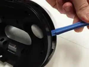
Slowly pry around the black internal housing using an opening tool.
-
Pull the loosened black lid away from the back housing.
-
-
-
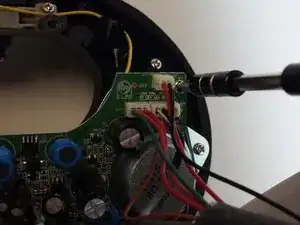
Locate the green circuit board on the back of the black lid.
-
Remove the four 8 mm Phillips #1 screws securing the circuit board using a Phillips #1 Screwdriver. The screws are located at the four corners of the board.
-
-
-
Remove the single 8 mm Phillips #1 screw using a Phillips #1 Screwdriver.
-
Pull the speaker port (the large black tube) off the main black housing.
-
-
-
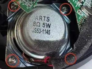
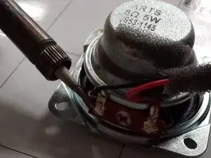
Remove the four 7 mm Phillips #1 screws holding the speaker in place using a Phillips #1 Screwdriver.
-
-
-
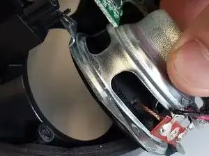
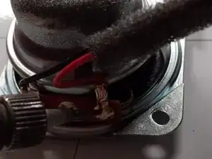
Carefully score an inch of the black sponge insulation with a wire cutter.
-
Gently pull the foam away from the wires.
-
-
-
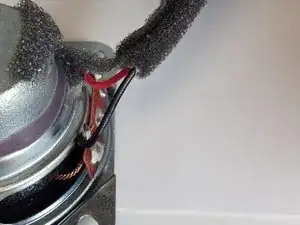
Heat up the solder securing the red wire using a soldering iron.
-
Remove the red wire.
-
Remove the black wire through the same process.
-
-
-
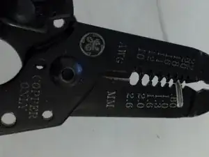
Strip a quarter inch of rubber insulation from each of the speaker wires (red and black) using a wire stripper’s 0.80 mm wire gauge.
-


To reassemble your device, follow these instructions in reverse order.
One comment
i hardly difficult to treat 2 defective speakers. i find the flat cable a little loose on the main plate. thank you!!!