Introduction

Follow this guide to replace the power supply in your PlayStation 5 Pro.

If your PlayStation isn't turning on, has intermittent power, or randomly shuts down, it might be time to replace the power supply.

  1. wHVpAPalMtKCWbdb
    wHVpAPalMtKCWbdb
    MSKoyDTWRhTwUdVo
    PQeie6NiddUFrABX
    • Before starting your repair:

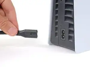
    • Shut down your PlayStation and unplug all cables and accessories.

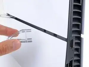
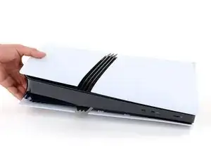
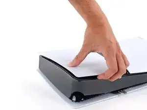
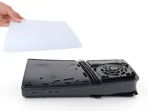
    • Remove any stands supporting your console and lay it down so the right side is facing up.

  2. CFW3QLi2CWBVvtGZ
    CFW3QLi2CWBVvtGZ
    pfX1qxAQi5bVEYeg
    gJNT2AlTWJWiPASh
    • Each console cover is secured with hooks along the rear edge and clips along the front edge.

    • To remove a cover, firmly pull up the front edge to release the clips.

    • You'll hear distinct "pops" as the clips release.

    • Remove the cover.

  3. EHKNY4Os6Jqg3iFo
    EHKNY4Os6Jqg3iFo
    GogShOwXX6Tf6Fpl
    nDceYNDJrCVOhWLb
    • Use the same process to remove the three remaining covers.

    • To reinstall a cover, place the hooks into their cutouts along the rear edge and firmly press the front edge of the cover into place to re‑engage the clips.

  4. syrUTZ2gdxIxtsVJ
    syrUTZ2gdxIxtsVJ
    UaSADHXS5MADFQow
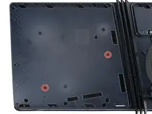
    • Use a T8 Torx Security screwdriver to remove the two 21.5 mm‑long screws securing the power supply.

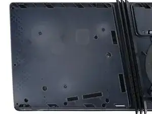
    • Flip your PlayStation over.

  5. jSvmTWU4XgQLNXOh
    jSvmTWU4XgQLNXOh
    An2u23cXafS2TR4K
    • Throughout this repair, keep track of each screw and make sure it goes back exactly where it came from.

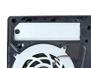
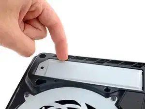
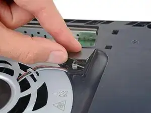
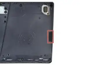
    • Use a Phillips screwdriver to remove the 17.1 mm‑long screw securing the expansion slot cover.

  6. 2kSqR3tLphnInaZW
    2kSqR3tLphnInaZW
    MejFxTYVGQPKZBZU
    k4ZeZTS6ra6bPZuT
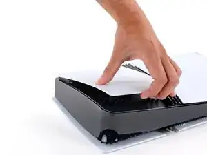
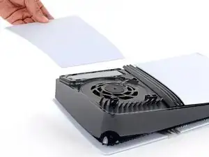
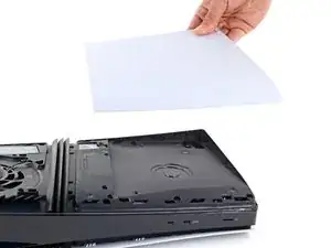
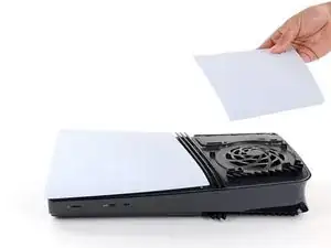
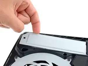
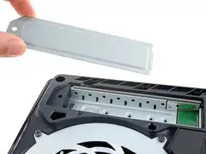
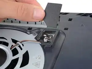
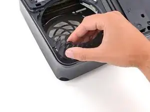
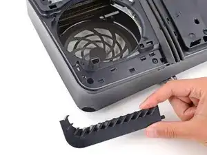
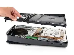
    • Use your fingers to lift the expansion slot cover near the notch by the screw hole and remove it.

  7. Haf4mDbsJlSLAnEJ
    Haf4mDbsJlSLAnEJ
    JxIpwPODeUS6vMCO
    H4X1RGawjrOXxgxV
    • Use your fingers to remove the plastic cover hiding the fan cables connector.

    • The cover is secured with light adhesive.

    • During reassembly, press the piece of plastic back into place to secure it with the leftover adhesive. If it isn't sticking, use strips of double-sided tape to secure it.

  8. nq1rhobOjJPUN2fw
    nq1rhobOjJPUN2fw
    ZhcuKNQLRioMLLTX
    • Gently pull the fan cables out from under their plastic clip on the frame.

  9. 4UtHMkosrW32eE2P
    4UtHMkosrW32eE2P
    ZTPMZoohZSjNRxR1
    uKcstxPpUvImCrDg
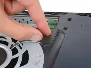
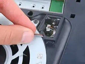
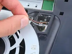
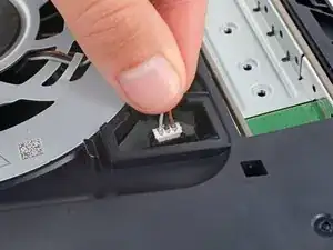
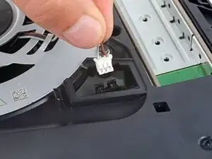
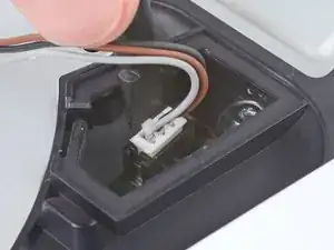
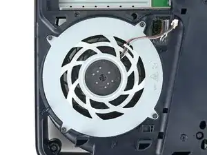
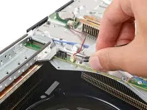
    • Firmly grip the fan cables' white connector head and pull it straight up and out of its socket.

    • If you're having trouble, grip the cables just above the connector head, and gently pull.

    • During reassembly, align the connector over its socket and push down on the edges with the flat end of a spudger until it slides fully into its socket.

  10. G6FDJPZDhpSTGHWW
    G6FDJPZDhpSTGHWW
    SMTt6aJ2WGKsWGlC
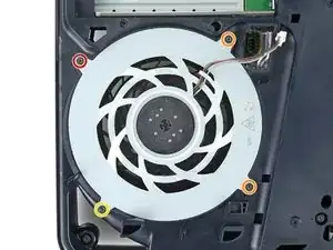
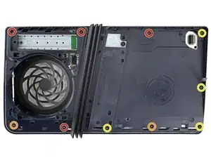
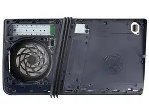
    • Use a T8 Torx Security screwdriver to remove the four screws securing the fan:

    • One 31.7 mm‑long screw

    • Two 21.5 mm‑long screws

    • One 11.5 mm‑long screw

  11. b5obnDWhkEuIQ26R
    b5obnDWhkEuIQ26R
    5yDx2x1QL3GSS6gi
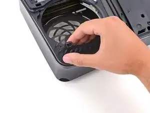
    • Use your fingers to grab the fan by its vents and lift it straight up to remove it.

    • During reassembly:

    • This is a good point to clean the fan. Use a clean cloth and some compressed air to remove any dust or dirt.

    • Insert the fan so its cables are near their connector.
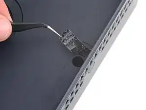
  12. NsFGlea23PqWHMBr
    NsFGlea23PqWHMBr
    n2oA1ydvBGYabPjg
  13. UhcyANUjMWWFkLhK
    UhcyANUjMWWFkLhK
    LBCgJWfVKlLgusEE
    2IErB2WDBHDPUGRt
    • Use your fingers to unclip and remove the plastic grille near the fan recess.

  14. BrBmdSSyWaZMOguE
    BrBmdSSyWaZMOguE
    OTaiNvGFfPEOEnsL
    • Use a T8 Torx Security screwdriver to remove the 10 screws securing the right‑side inner shell:

    • Four 18.8 mm‑long screws

    • Two 18.6 mm‑long screws

    • Four 31.7 mm‑long screws

  15. tkEYTLiolgQ5OCKu
    tkEYTLiolgQ5OCKu
    WSi2WL3QUyIUTrch
    • Lift the right‑side inner shell straight up and remove it.

  16. fHOPnfBuhPNUYotP
    fHOPnfBuhPNUYotP
    h1pYhZQohIbIMPug
    yejBbL23qlaVFhWy
    • Use a pair of angled tweezers to firmly grip the sides of the CMOS board connector, holding the tweezers as close to the connector as possible to get a good grip.

    • Pull the connector straight up and out of its socket to disconnect it.

    • If you're having trouble, try rocking the connector side-to-side to loosen it.

  17. 2BSHDAavtBygAQaJ
    2BSHDAavtBygAQaJ
    xt5iRO1JQptZhhLJ
    HcEPV2SJtirsbRHb
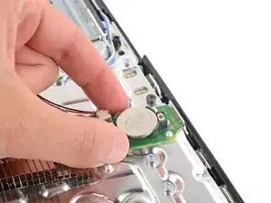
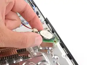
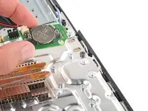
    • Use your fingers to lift the CMOS board off the small metal nubs and pull it toward the center of your console to remove it.

    • If your new board doesn't come with a cable, transfer the original cable to your replacement board.

  18. 1sSNEMeAMjeDxMfM
    1sSNEMeAMjeDxMfM
    YPRKFXQKBRYdgnHW
    acWDDCt3YOM4JpUT
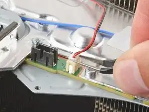
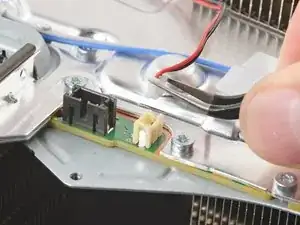
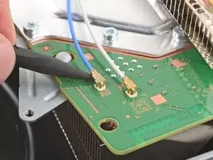
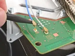
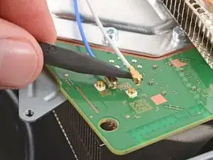
    • Insert a spudger under the metal neck of one of the antenna cable's coaxial connectors and lift straight up to disconnect it.

    • Repeat the process to disconnect the other antenna cable.

    • During reassembly:

    • Use the markings on the board to reconnect the antenna cables to the correct sockets—connect the blue cable to the socket marked RB and the white cable to the one marked RW.

    • To reconnect a cable, hold the metal connector head over its socket and press down with the flat end of a spudger until the connector snaps into place. Don't try to force the connector into place. If you're having trouble, reposition the connector and try again.

  19. WwAOeOEoC21nRFPV
    WwAOeOEoC21nRFPV
    lPyKUDZITaIa3xuM
    kyykClqFKCqwWvLg
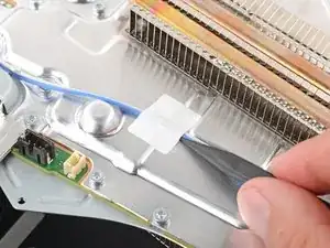
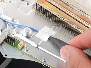
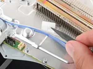
    • Use the point of a spudger to flip up the small piece of white tape securing the antenna cables to the metal shield.

  20. iyqsxoXsuKjAyWY1
    iyqsxoXsuKjAyWY1
    srckeh5AMwCxhuW1
    Xg4BebJPhT3XX2pY
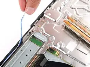
    • Use your fingers to de‑route the antenna cables from their clips on the metal shield.

    • Move the antenna cables over the side of your PlayStation so they're out of the way.

  21. rWYCCYxPFKerFpKK
    rWYCCYxPFKerFpKK
    guBgFuYDDTNVDqkh
    EFDtAZtGXfVuVVJG
    • Thermal paste bonds the bottom heat sink fins (closest to the power button) to the metal shield. Depending on the age of your device and condition of the thermal paste, separating the heat sink may take some force.

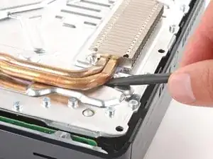
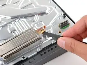
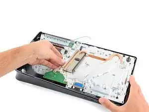
    • Insert the flat end of a spudger under the bend in the copper pipes, near the heat sink's bottom edge.

    • Use your spudger to pry up the heat sink, applying steady pressure to separate it from the thermal paste.

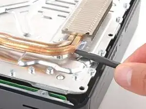
    • If the heat sink doesn't fully separate, use your spudger to pry up the bottom edge on the other side of the metal fins.

  22. TR4wTRXWiDsnfUMe
    TR4wTRXWiDsnfUMe
    ebwTVYFsVV6pmOfO
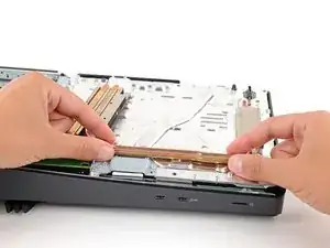
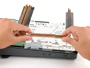
    • Grip the heat sink by its copper pipes and remove it.

    • Don't grip the sharp, metal fins on the heat sink.

    • During reassembly:

    • Before removing any of the old thermal paste, note the location and quantity of thermal paste on the metal shield. This way you'll know how much to use when replacing it.

    • Use the flat end of a spudger to scrape up and remove as much of the old thermal paste as possible.

    • Remove all the remaining thermal paste and its residue with high‑concentration (>90%) isopropyl alcohol and a microfiber cloth.

    • Apply new thermal paste where the old paste was.

    • Firmly push the heat sink into place.

  23. vfG2PVXvA1gxRu5Y
    vfG2PVXvA1gxRu5Y
    32fMwErEMnCD3ISo
    ctjiCbdI2kQuwEsJ
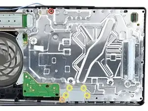
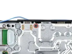
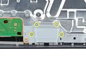
    • Use a T8 Torx Security screwdriver to remove the six screws:

    • One 11.5 mm‑long black screw securing the main board assembly

    • One 28.7 mm‑long screw securing the interconnect cable cover

    • Four 7.5 mm‑long screws securing the interconnect cable cover

  24. XVLeCDFJQ3CHvQMl
    XVLeCDFJQ3CHvQMl
    MLZIcWeHTFBtJZd6
    • Remove the interconnect cable cover.

  25. QZ23vCcCxWmPJ2b5
    QZ23vCcCxWmPJ2b5
    IUmXRtwGhcd61d1U
    fgvK6VMunANTBkRJ
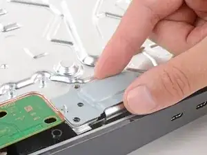
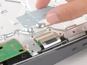
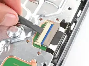
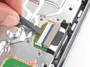
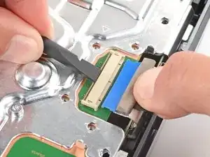
    • Use the flat end of a spudger to push down the metal bar on the interconnect cable socket.

    • With the metal bar held down, use your fingers or tweezers to grip the plastic pull tab and slide the cable straight out of its socket.

    • During reassembly, insert the interconnect cable into the socket until it snaps into place.

  26. 41fRrCdWkwrSaLcR
    41fRrCdWkwrSaLcR
    rb2KxQmkTZedKCPu
    • The power supply is connected to the bottom of the main board assembly by metal prongs that plug into the bottom left corner.

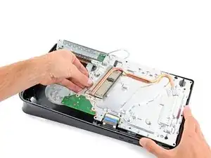
    • Lift the bottom left corner of the main board assembly off its gray plastic post. Keep the assembly lifted for the next step.

    • Your PlayStation's plastic housing will likely flex while lifting the assembly.

  27. GZH24hFQAK2GA3EU
    GZH24hFQAK2GA3EU
    6GZabOleu1LmTCFf
    wQhOmmt3BSHZfKxY
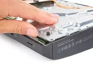
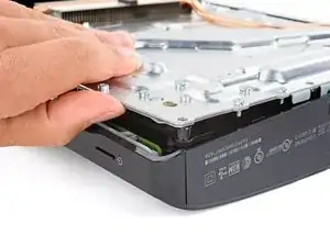
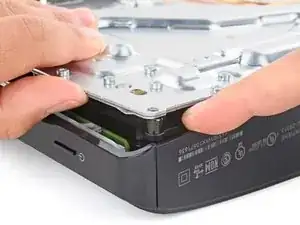
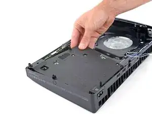
    • Keep the main board assembly raised with one hand.

    • With your free hand, insert your finger between the assembly and power supply.

    • Push down on the power supply and lift the assembly to separate them.

    • It'll take a significant amount of force to separate the two.

    • During reassembly, press down firmly on the bottom left corner of the main board assembly to fully connect it to the power supply.

  28. CXJ525ByGaKgj6DM
    CXJ525ByGaKgj6DM
    Dl3qNjeSMdvvOfhQ
    eQ3tNFVFwvU5YpSR
    • Do not grab the main board assembly by the copper heat pipes or its fins, as they can easily be damaged.

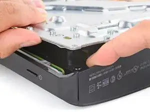
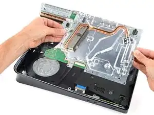
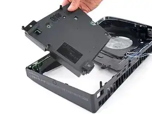
    • Firmly secure the plastic housing with one hand.

    • With your free hand, grab the upper edge of the main board assembly and lift it out of the plastic housing.

    • During reassembly:

    • Make sure the interconnect cable doesn't get stuck under the main board assembly when lowering it into place.

    • Lower the assembly into its recess so its prongs go into their socket on the power supply and the two cutouts go over their alignment posts.

  29. RbdSBGCYQ1dSXpNM
    RbdSBGCYQ1dSXpNM
    BvubUe2PQYty2EZe
    DcnAg25oEvIERCut
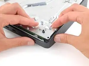
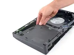
    • Lift the left edge of the power supply and remove it.

    • During reassembly:

    • Insert the power port into its cutout on the back of your PlayStation.

    • Lower the power supply into its recess, making sure the cutout on the bottom left corner goes over its plastic post.

Conclusion

To reassemble your device, follow these instructions in reverse order.

Take your e-waste to an R2 or e-Stewards certified recycler.

Repair didn’t go as planned? Try some basic troubleshooting, or ask our Answers community for help.

Spencer Day

Member since: 14/09/22

95592 Reputation

0 comments