
Introduction
This guide takes you through the process of installing the motherboard.
-
-
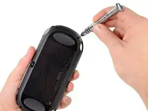
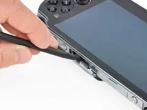
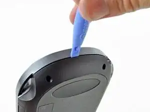
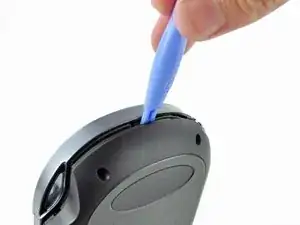
Using your fingernail or a spudger, pry open the accessory port cover on the top of the device.
-
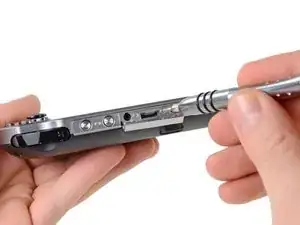
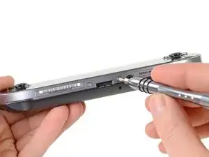
Using a Phillips #00 screwdriver, remove the two 5.4mm screws hidden beneath the accessory port cover.
-
-
-
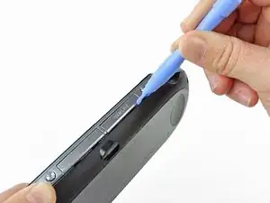
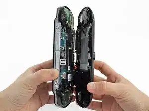
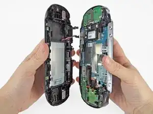
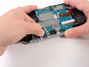
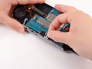
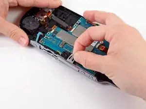
Beginning at the sides of the device, use a plastic opening tool to separate the front and rear cases.
-
Continue working your way around the device gently prying it open.
-
-
-
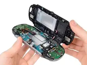
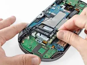
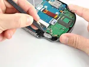
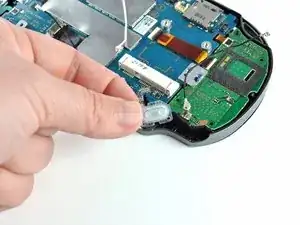
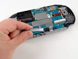
Gently separate the two cases, minding the battery and the touch screen controller connectors holding the two cases together.
-
-
-
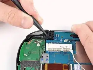
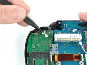
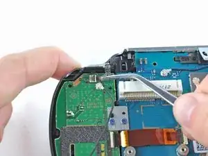
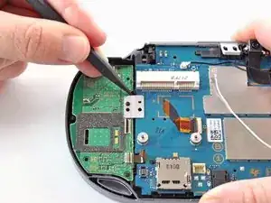
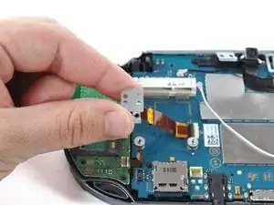
Using a spudger, free the touch screen controller flex cable by gently prying up the connection.
-
-
-
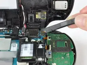
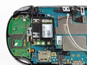
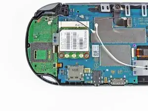
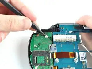
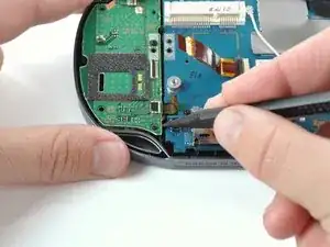
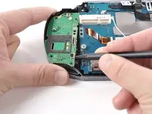
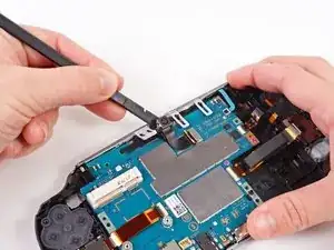
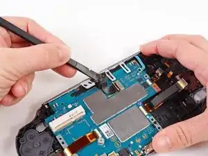
Using the pointy end of the spudger, disconnect the three antenna cable connectors on top of the wireless card.
-
Deroute the antenna cables so that they are out of the wireless card casing. Rest the wires out of the way.
-
-
-
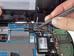
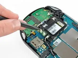
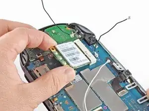
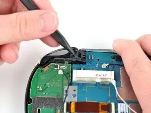
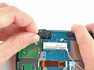
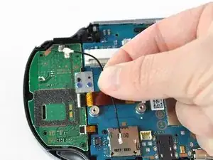
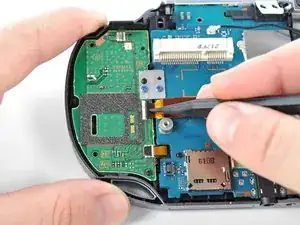
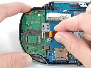
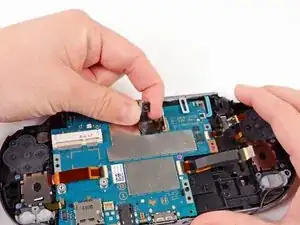
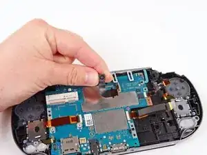
Hook the spudger beneath the tab on the wireless card casing and release the tab.
-
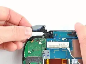
Peel up and remove the wireless card casing.
-
-
-
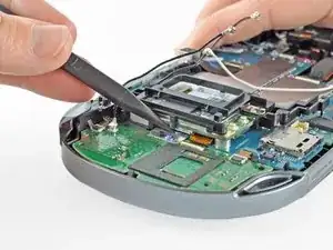
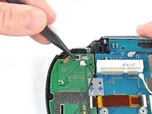
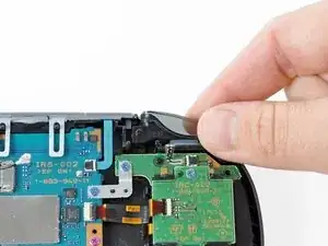
Using a spudger, gently peel up the right shoulder button from the light adhesive connecting it to casing.
-
-
-
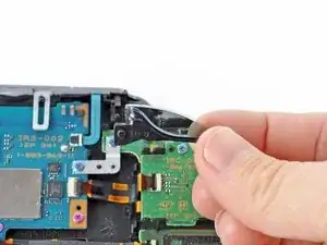
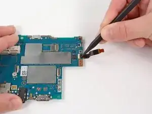
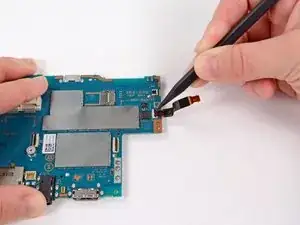
Using the pointy end of a spudger, detach the antenna cable on the right button board.
-
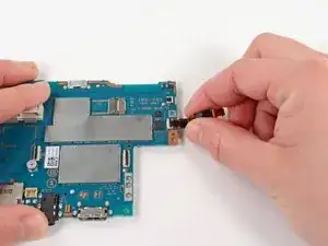
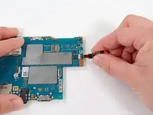
Remove the antenna cable.
-
-
-
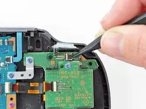
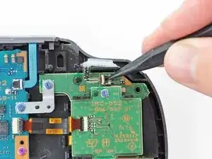
Using a spudger, pry up and release the ZIF socket on the right button board.
-
Gently pull the flex cable out of the socket. Rest the flex cable out of the way.
-
-
-
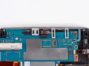
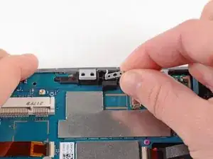
Remove the two 5.0mm Phillips #00 screws from the metal bracket securing the right button board to the motherboard.
-
Remove the metal bracket, using a spudger as necessary to lift it out.
-
-
-
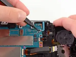
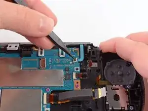
Use a spudger to free the right button board by prying up from the bottom right corner of board.
-
Gently lift the right button board out.
-
-
-
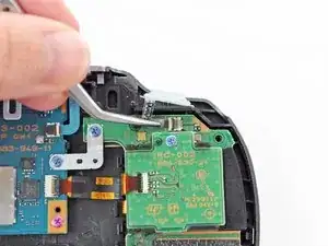
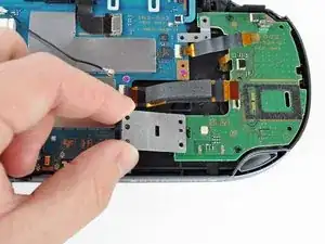
Pry up the left shoulder button casing with a spudger.
-
Remove the left shoulder button casing.
-
-
-
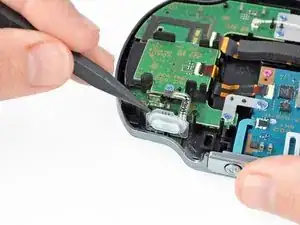
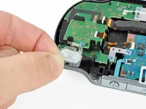
Using a spudger, gently peel up the left shoulder button from the light adhesive connecting it to casing.
-
-
-
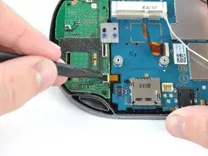
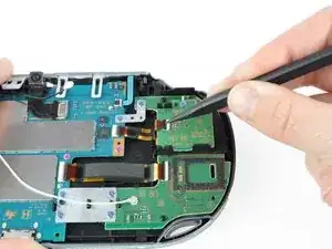
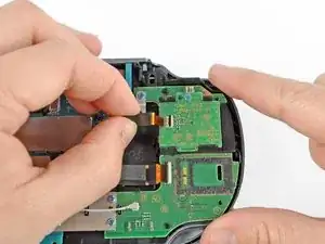
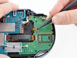
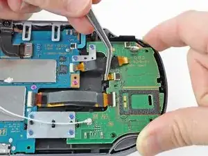
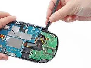
Using a spudger, lift and release the tab on the ZIF socket sitting on the SIM card reader.
-
Carefully pull the flex cable out of the ZIF socket, and rest it out of the way.
-
-
-
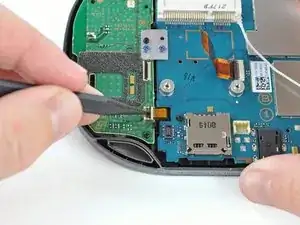
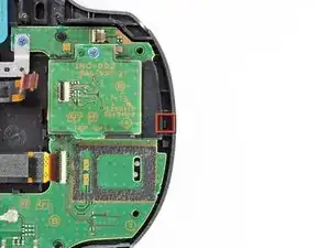
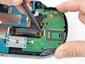
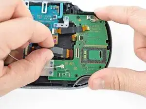
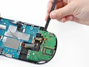
Use a spudger to release the tab between the SIM card reader and the back casing assembly.
-
Lift the SIM card reader off the back casing assembly.
-
-
-
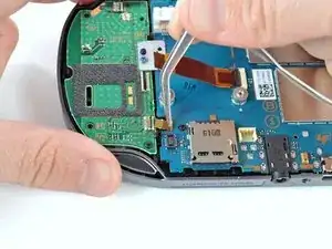
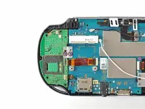
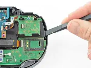
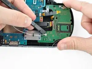
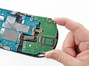
Use a spudger to lift up the tab on the large ZIF socket.
-
Gently pull the flex cable out of the ZIF socket, and rest it out of the way.
-
-
-
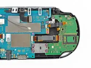
Using a Phillips #00 screwdriver, remove the six screws on the two metal brackets:
-
Two 5.0mm, blue screws on the L-bracket securing the upper left button board to the motherboard.
-
Four 5.0mm, blue screws on the square bracket securing the lower left button board to the motherboard.
-
-
-
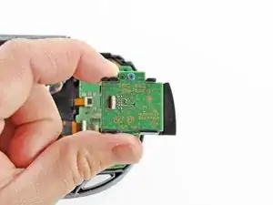
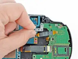
Starting from the upper left corner, use a spudger to pry up and remove the left button board.
-
-
-
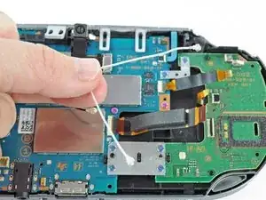
Using the pointy end of a spudger, pry up and release the GPS antenna cable from the motherboard.
-
Remove the GPS antenna cable.
-
-
-
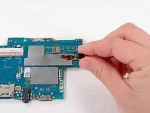
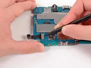
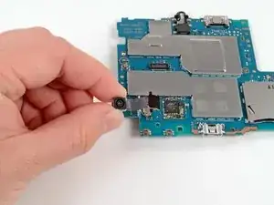
Using a spudger, gently pry up on the camera.
-
Work your way under the camera and along the camera flex cable, using the spudger to peel away the adhesive, freeing the camera.
-
-
-
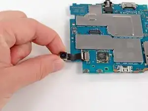
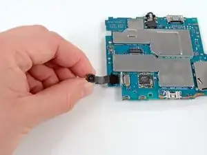
Carefully lift and remove the camera, sliding the flex cable out of the open connector socket.
-
-
-
Using a Phillips #00 screwdriver, remove the 6.3mm screw beneath the camera.
-
Lift and remove the metal camera bracket.
-
-
-
Using a Phillips #00 screwdriver, remove the two pink, 4.4mm screws securing the motherboard.
-
-
-
Gently peel the rubber tab of the game port cover off the plastic casing pins.
-
Remove the game port cover.
-
-
-
Gently peel the rubber tab of the accessory port cover off the plastic casing pins.
-
Remove the accessory port cover.
-
-
-
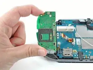
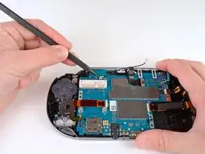
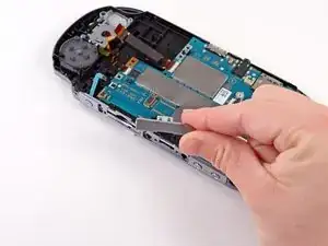
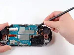
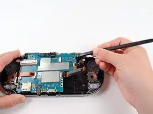
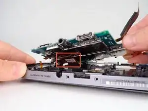
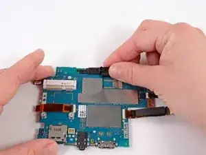
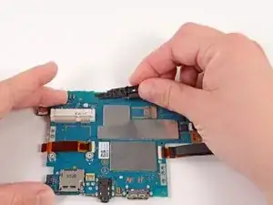
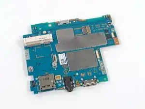
Starting at the upper right hand corner, use a spudger to gently lift the motherboard out of the casing assembly.
-
-
-
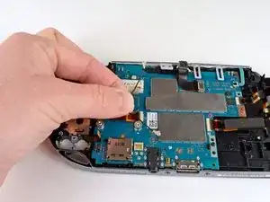
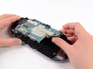
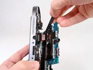
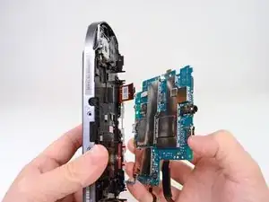
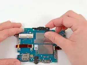
Lift the motherboard out and identify the OLED connector still attaching the motherboard to the casing.
-
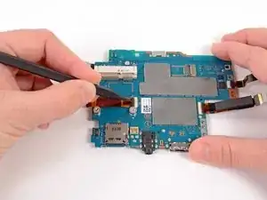
Holding the Vita on its side, use a spudger to gently pry off the OLED connector from the motherboard.
-
-
-
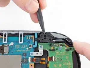
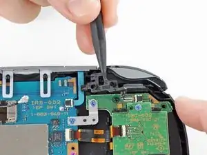
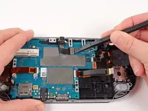
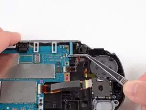
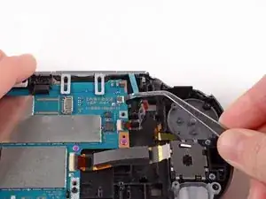
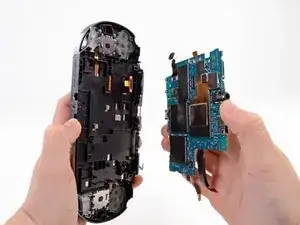
Starting at the right side, gently lift and remove the black casing that once held the camera.
-
-
-
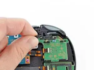
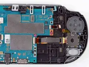
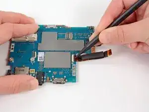
Using a spudger, release the tab on the ZIF connector located above the two screw posts where the wireless card once was.
-
-
-
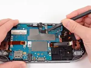
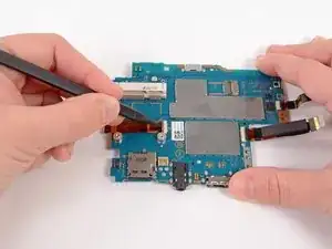
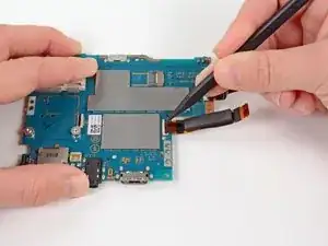
Release the tab on the large ZIF connector on the right side of the motherboard by lifting the tab with a spudger.
-
-
-
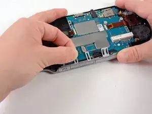
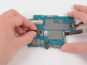
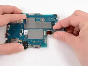
Flip the motherboard over.
-
With the help of a spudger, pry up and release the tab of the rear camera flex cable connector.
-


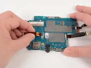
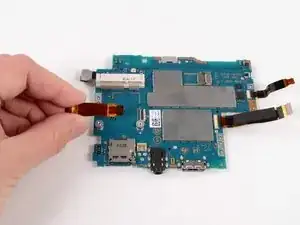
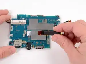

To reassemble your device, follow these instructions in reverse order.

11 comments
in steps 2&3, bottom is top and top is bottom
it should be noted that the memory card should always be taken out before separating the case. I just broke my memory card slot by having a card in there while I was opening the case, there's a tiny bit of overhang that will pull the slot off the motherboard.