Introduction

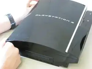
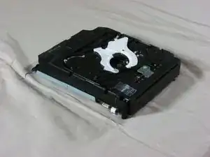
This guide explains how to take apart the Sony PlayStation 3 optical drive. These steps are useful for repairing or replacing the optical drive.

  1. rRVTEQvQSS5Ze1Rn
    rRVTEQvQSS5Ze1Rn
    qTHOsnNlmBUOWhAD
    • Remove the rubber screw cover near the hard drive cover with a spudger.

  2. jWkgTH6jmueQ2UjL
    • Remove the screw holding the top cover in place with a Torx T10 screwdriver.

  3. LJVdBODLxElDdjJt
    LJVdBODLxElDdjJt
    fT2KSo6Koxg1O4tk
    • Slide the top cover down about half an inch.

    • Lift the cover off of the PS3.

  4. MK4IGe6IynEYoUju
    MK4IGe6IynEYoUju
    MLLXH46mEHgnCndi
    • Remove the seven screws in the top cover with a Phillips #2 screwdriver.

    • One of the screws is shorter than the others. The short screw is marked in yellow.

    There is two additional small screws that need to be removed similar than the yellow one.

    Enrique Basulto -

  5. NEP2c1OvPEUPganR
    NEP2c1OvPEUPganR
    nN4ebyTIWAZNZDyh
    JVcgo4sKFKXtUYVr
    • You can now lift off the top cover.

  6. HlYK24e1ERNsAZqV
    HlYK24e1ERNsAZqV
    inUifwj3oIEelvtm
    Bmxj4nfOHHU4VEFk
    • Lift the optical drive enclosure and disconnect the grey wires.

    • Do not lift it too far up before disconnecting the wires.

  7. 5INTa2BVsCVgWiEF
    5INTa2BVsCVgWiEF
    6HfNgIFVDuOITXxr
    Tnpu5niZQIYP6dpF
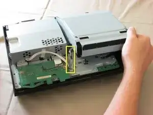
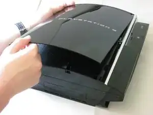
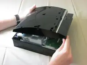
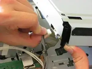
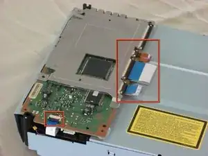
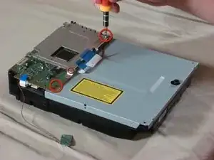
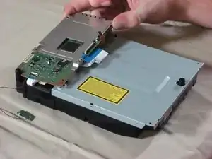
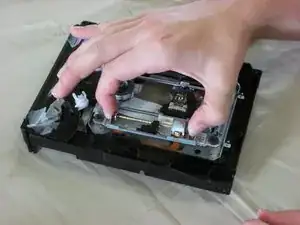
    • Tilt the front of the optical drive enslosure upwards.

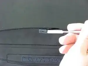
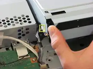
    • Lift the black ribbon cable latch on the back side with your finger or a spudger.

    • Disconnect the ribbon cable.

  8. Uk1dUpRvI3T6umQv
    • Remove the optical drive enclosure from the PS3.

  9. c1bqKyCkfIVKJwNm
    c1bqKyCkfIVKJwNm
    MiGLJaMxaqIaMDbu
    HJPQKdmVbNannnMN
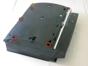
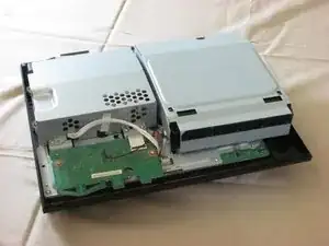
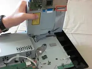
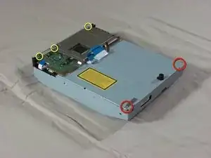
    • Flip over the optical drive enclosure. There are four ribbon cables connected to the circuit board. Using a spudger or your finger, lift each ribbon cable latch and disconnect each ribbon cable.

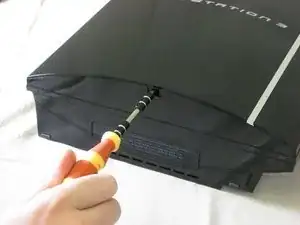
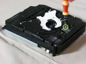
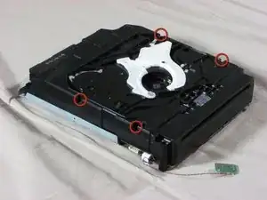
    • Remove the three screws on the board with a Phillips #00 screwdriver.

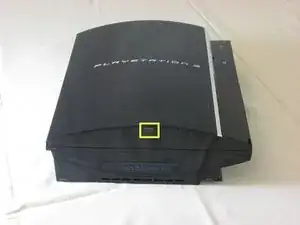
    • Remove the two silver screws on the bottom of the case. These screws are different from the ones on the board and should be kept separate.

    • Note: The longer of these two screws holds down a metal tab that comes loose as seen in the third picture.

  10. U6lAkW4oLFXUNuGw
    U6lAkW4oLFXUNuGw
    TiawNnTNocRrFWmN
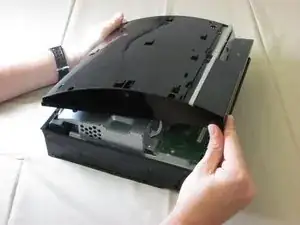
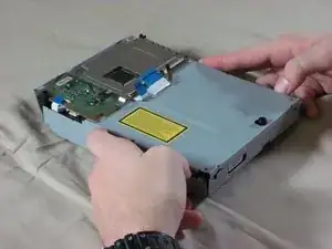
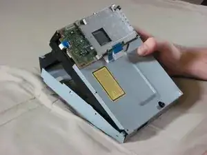
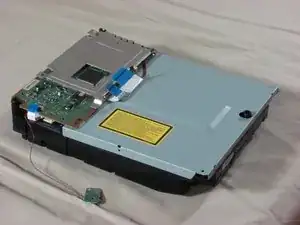
    • Using your thumbs, carefully bend out the sides of the metal enclosure.

    • Lift the plastic enclosure out of the metal enclosure.

  11. ZVymASFGnlxXG3fT
    ZVymASFGnlxXG3fT
    GXqhkB3n4yBAy1pJ
    kFfbuWrp2VIkuHHc
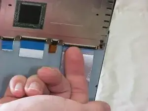
    • Flip over the enclosure so that the circuit board is on the bottom and the optical sensor is on top.

    • Remove the screw on the optical sensor using a Phillips #00 screwdriver.

    • Remove the tape on the red and black wires that connect to the optical sensor. With the wires still attached, take the sensor off the ensclosure.

    • The wires on the optical sensor are very weak. They will break easily if excessive force is applied to them.

    • Remove the four black screws on the edges of the enclosure using a Phillips #00 screwdriver.

    • After taking out the screws, you don't have to open the enclosure just yet.

  12. yvAFr4lsIXerlK4e
    yvAFr4lsIXerlK4e
    NdNmN4GCwlXgRhyf
    • Flip over the enclosure again.

    • Remove the rest of the screws in the corners of the circuit board.

  13. 3dyQhX2PQQxpBptL
    3dyQhX2PQQxpBptL
    rx2Lj15UGrSCoFjp
    6gkDWqVLmhgUXCUd
    • Lift the circuit board off the enclosure.

    • The metal EM shield on the circuit board is loose, so make sure to keep it together with the circuit board.

    • Remove the metal plate.

  14. 1mKPBJADbGpUsMyA
    1mKPBJADbGpUsMyA
    uYunBII3yeGmplgA
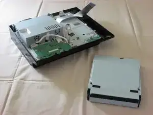
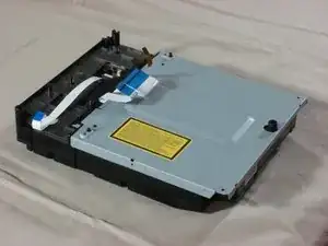
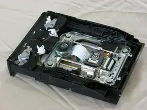
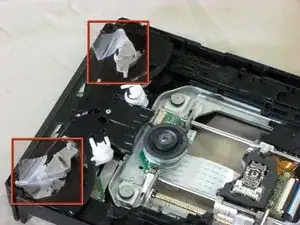
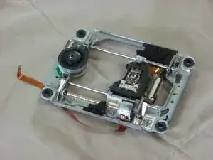
    • Flip over the enclosure. Remove the black, plastic cover so that the drive and its enclosure match the first picture.

    • Proceed carefully. There are loose parts inside the optical drive. We recommend that you tape these parts.

  15. dl1e3eLZKPakElGh
    dl1e3eLZKPakElGh
    lcnjXDS2DvbEKQpF
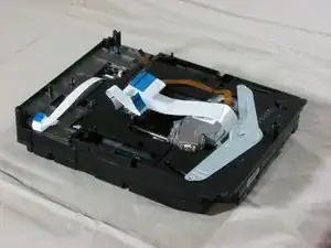
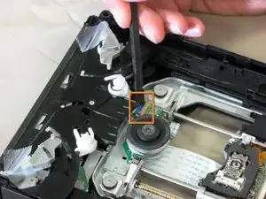
    • Using a spudger, lift the brown latch and disconnect the small ribbon cable.

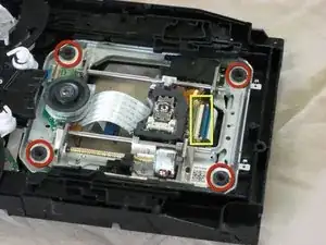
    • Remove the four fat screws in the corners of the optical drive.

    • Using a spudger, lift the black latch and disconnect the larger ribbon cable.

  16. veHTbTTU34FxYHZN
    veHTbTTU34FxYHZN
    VGYycsscy1dHWVvs
    • Carefully lift the optical drive out of the enclosure.

Conclusion

To reassemble your device, follow these instructions in reverse order.

iDeleted

Member since: 07/07/10

2101 Reputation

One comment

When reassembling it there is a key part that needs to be exactly inline. see this video for help: http://www.youtube.com/watch?v=hzHPRGHFj...

Paddy -