Introduction
This guide is intended to show you how to replace the power button on the RazorX DLX Electric Skateboard. The power button is a temporary switch that allows the battery to supply power to the motor. The power button is necessary to ensure safety and longevity of the battery itself. While troubleshooting be careful when handling wires and the circuit board. Before you start, make sure the device is powered off.
Tools
-
-
Flip the skateboard upside down.
-
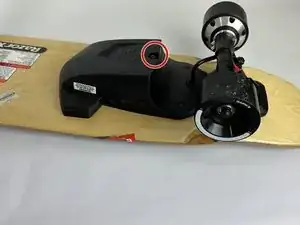
Use a 4 mm Allen key to remove the 25 mm bolt that secures the cover.
-
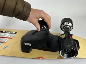
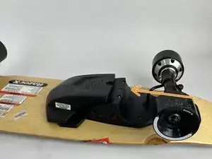
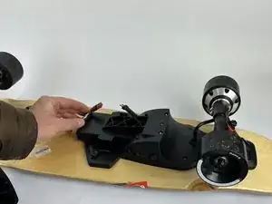
Push the cover forward to slide it off.
-
-
-
Flip the skateboard back over.
-
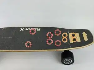
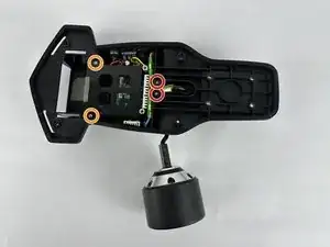
Remove the six 22 mm bolts indicated on the top side of the skateboard with a 3 mm Allen key.
-
While holding the nut from the underside of the skateboard remove the four 32 mm bolts with the 3 mm Allen key.
-
Separate the trucks and control module from the board.
-
-
-
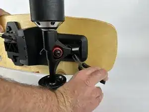
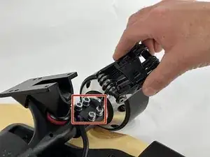
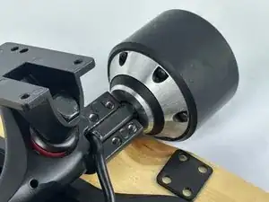
Remove the four 20 mm bolts using a 4 mm Allen key, then remove the metal plate to separate the motor from the trucks.
-
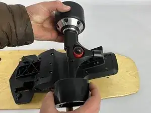
Separate the wheel motor from the trucks
-
-
-
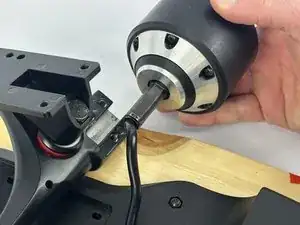
Remove the two 15 mm Phillips #00 screws to free the motor cable.
-
Remove the two 15 mm Phillips #00 screws securing the battery cage.
-
-
-
Remove the two standoffs holding the battery cage in place with an 8 mm wrench.
-
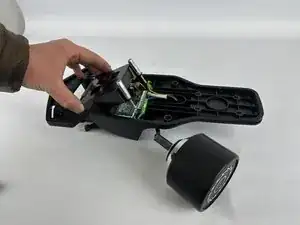
Lift the battery cage up and out of the control module.
-
-
-
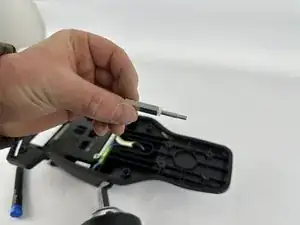
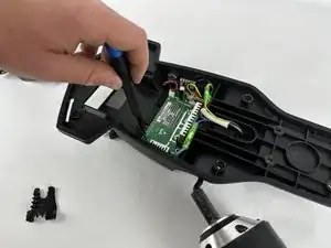
Remove the 20 mm Phillips #0 screw.
-
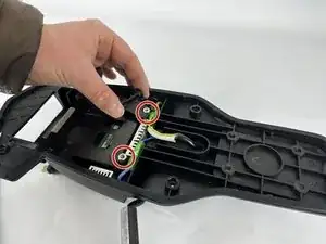
Disconnect the DC connector. The DC connector can be identified as the connector with only two wires.
-
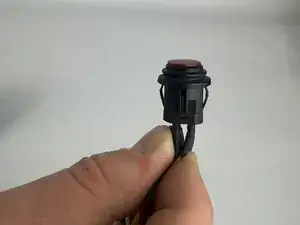
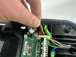
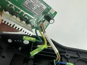
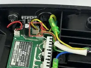
Disconnect the power button. It is a temporary switch, which can be identified by its 4-wire configuration.
-
Disconnect the Hall effect sensor. It can be identified by its 6-wire configuration.
-
-
-
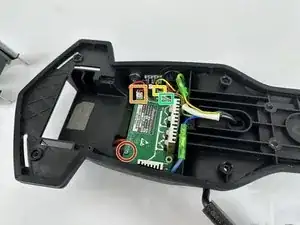
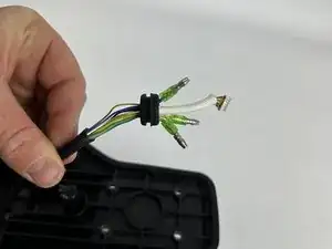
Disconnect the power button from the control module.
-
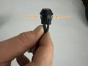
Pinch the two plastic tabs to remove the power button from the plastic body.
-

To reassemble your device, follow these instructions in reverse order.