Introduction

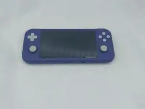
If the device is not turning on at all and is not responding, follow this guide to do a mainboard replacement (PCB) on the device. This process will take approximately 20-25 minutes, and the tools needed for the project are listed in the guide.


  1. NoyTpQYKgrBqUnYq
    • Unplug any cables connected to the Retroid Pocket 3+.

    • Ensure your device has a charge of 5% or less as a charged battery can be dangerous if punctured.

  2. SJWM3mXSyA4rmts4
    SJWM3mXSyA4rmts4
    QHsiZWqRyZqMqpm1
    LcGnolvQgfOyXdhn
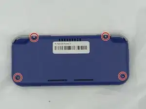
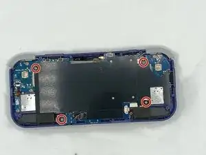
    • Remove the four 6 mm screws from the backplate of the device with a T5 Torx screwdriver.

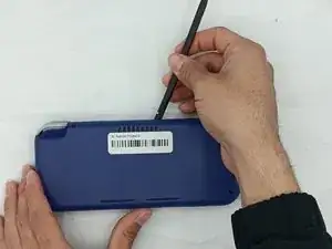
    • Use a plastic opening tool or spudger to gently pry apart the backplate from the device.

  3. UtrYjlWQ5LYY5iHS
    UtrYjlWQ5LYY5iHS
    nrfICOX5FkOwMhfw
    • Remove the four 4.5 mm screws with a Phillips #00 screwdriver.

    • Lift off the metal plate.

  4. ACaHbojOqJPIviuW
    ACaHbojOqJPIviuW
    ggJ3kjOWMIjYmbKX
    cJCU5TXw2EOYgyR4
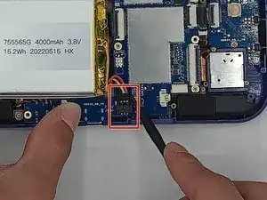
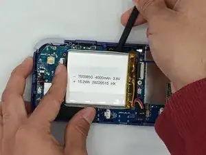
    • Use a plastic opening tool or spudger to unclip the battery connector.

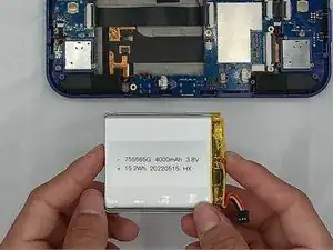
    • Carefully lift the battery from the case.

    • The battery has double-sided tape at the bottom. Gently push a spudger or opening tool underneath the battery to help free it from the adhesive. Do not bend or puncture the battery.

    • Lift and remove the battery.

  5. Y1ePAEOwB5JRHi6G
    • Remove the three 4.5 mm screws with a Phillips #00 screwdriver on the main board.

  6. aL1Bw4BvphbfPWkj
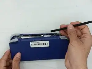
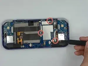
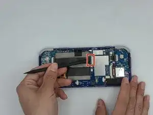
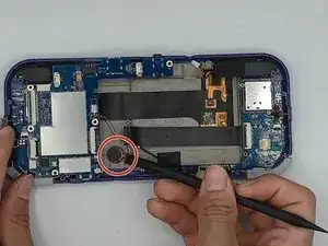
    • Using a spudger, put the tip under the aerial connecter and rotate upwards to unclip the plug.

  7. tTTw3EKPcvYTuGGl
    • Unclip and remove the one ribbon cable on the left.

  8. EZTTEKegKe5xpTMA
    • Use a spudger to unclip and remove the two ribbon cables on the right side.

    There is one more ribbon cable that is not called out on this diagram. Right side, between the two in step 8. Appears to be a 5 pin ribbon cable going up into the connector.

    Chris Fulton -

  9. 2UOuJ4CvrwfEnC4O
    2UOuJ4CvrwfEnC4O
    vUNQYcHMjyXekrWG
    • Use a spudger to disconnect the two speaker cables on the bottom of the board.

  10. hGFKLHXvZvOG2DcA
    hGFKLHXvZvOG2DcA
    PPNlBKDryGXCLXQw
    Ruf2pxJMXt4Z6idX
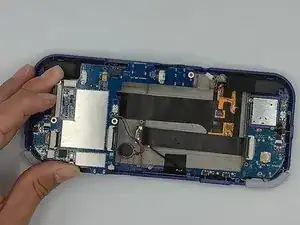
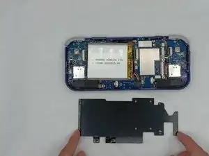
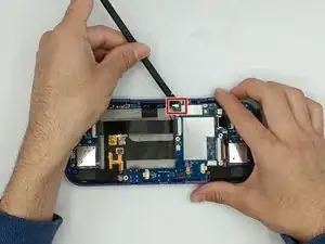
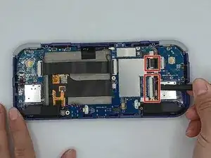
    • Start lifting the board to give you access to the vibration motor on the metal case.

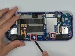
    • Use a spudger to carefully pry the motor free; it is bound with double-sided tape.

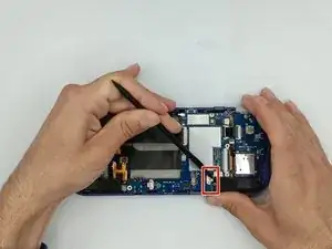
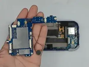
    • Carefully lift the board out of the device.

Conclusion

To reassemble your device, follow these instructions in reverse order.

Willem Pretorius

Member since: 08/02/24

183 Reputation

0 comments