Introduction

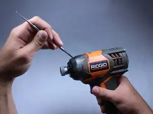
The trigger is a multi-speed switch and requires replacing the whole assembly. Soldering is necessary for this guide. Please familiarize yourself with the iFixit guide on Soldering before starting.

  1. lT32cBph1OcI6aB6
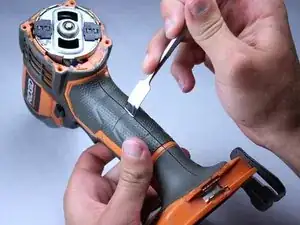
    • Use the flat side of a metal spudger to peel the black rubber cover off of the casing.

    • Use some force; the rubber cover is securely attached to the housing.

    • Rotate the casing until it fits onto the housing with no gaps between it and the clear cover.

    • Make sure the casing is properly oriented onto the housing. Orientation is important here.

  2. muWgkGaPyspu3vLv
    muWgkGaPyspu3vLv
    lVUXByNwbAttLqqc
    • Remove the plastic cover with your hands. It should come off fairly easily.

  3. 1YICKDHLy4yQ5O32
    1YICKDHLy4yQ5O32
    h6rMOCtdXb1aOjmR
    XiwlOyar3drlqZqT
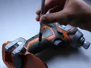
    • Unscrew the four 16 mm long screws from the back panel with a T10 Torx Screwdriver.

    • Use a firm grip to peel off the back panel. It is sealed tight and requires a good amount of force to remove.

  4. xtswKoSbnMsmPsdE
    xtswKoSbnMsmPsdE
    k36RHeRfWN3rBYOg
    • Unscrew the eight 15 mm T10 Torx screws from the housing

    • The screw hole located nearest the battery port is deep and small. Most screwdrivers with replaceable bits will not fit into the hole. Instead, use a conventional screwdriver that fits.

  5. hGfV6lrHXMhM4QsX
    • Place the driver flat on a table before completely separating the two halves of the housing so components of the drill don't fall out during opening.

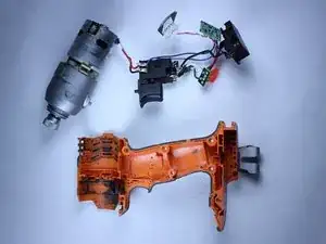
    • Pry apart the two halves of the housing at the back side of the driver using the metal spudger. The housing is easier to remove if you pry from both sides.

  6. Tnp11lKgGbNPMVIZ
    Tnp11lKgGbNPMVIZ
    eDnlpCdY42LiAb3U
    • Do not remove the direction switch.

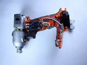
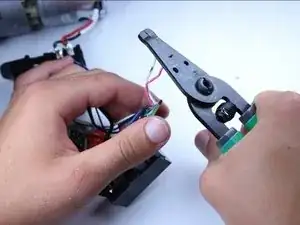
    • Pull out all electrical components from housing by hand. The components should require little force to lift out.
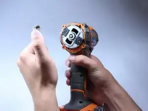
    • Lift out the motor.

    • Follow the wires.

    • The circuit board located nearest the battery pack and the LED light will be hard to pull out.

    • Remember to precisely place all components in their correct slots with their correct orientations when reassembling.

  7. kjhmcaOYhTYqWRCo
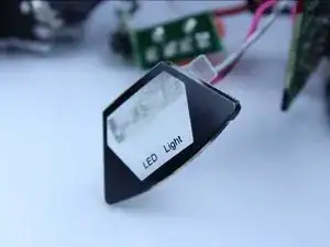
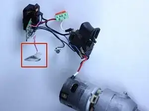
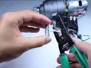
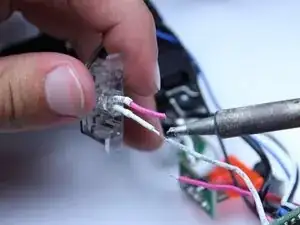
    • Identify the LED light. The LED light is the component with clear casing and has two wires attached, located toward the bottom of the driver.

  8. dGkHtGIR1wXabVAZ
    dGkHtGIR1wXabVAZ
    McsMWkGKGFDUcrRm
    X1XwigkCIYFlFHuR
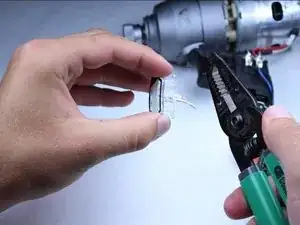
    • Cut the pink and white wires attached to the LED at a point that is a little more than 1/4 inch from the LED.

  9. QbH4eSj3mOtswyAi
    • Strip the wires back about 1/4 inch on the LED.

  10. QooqULsbjbQkxkff
    QooqULsbjbQkxkff
    HpLkkCaXxISIIeHc
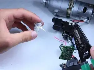
    • Strip the wires that were connected to the LED on the circuit board to approximately 1/4 inch.

  11. hcLQ1jReOWLYuKue
    • Solder the new LED striped wires to the wire attached to the circuit board.

    • Wrap the soldered connection with electrical tape, to ensure that the circuit isn't shorted.

Conclusion

To reassemble your device, follow these instructions in reverse order.

Sean Liston

Member since: 28/04/15

311 Reputation

0 comments