Introduction
The logic board is the "motherboard" of the camera that contains all of the main circuits and important components necessary to make the device run efficiently. If the logic board is old, faulty, or damaged, this may prevent the camera from working properly.
-
-
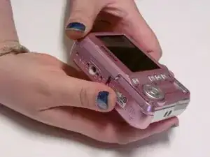
With the camera facing LCD side up, slide the battery compartment lid to the right.
-
Remove the old batteries.
-
-
-
Carefully pull the back case (the side showing the LCD screen) away from the front half.
-
There are clips securing the top of the back case. Do not be afraid to use the proper amount of force to remove the back case.
-
Turn the camera around to the front (the lens side). Carefully remove the front case.
-
There are also clips on the lens' side as well, so do not be afraid to use force.
-
-
-
Position the camera so the LCD screen is facing you.
-
Remove the LCD screen from the screen plate.
-
Replace the broken LCD screen with the functioning LCD screen.
-
-
-
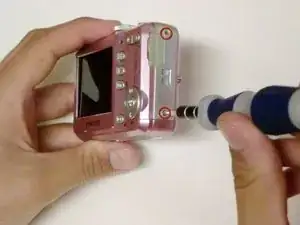
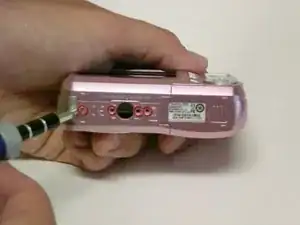
Using a #00 Phillips screwdriver, remove the six 4.3 mm screws along the edges of the camera.
-
Save them for putting the camera back together.
-
-
-
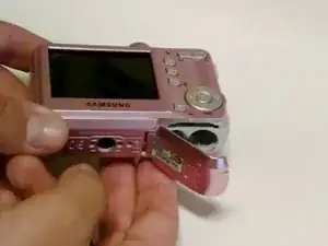
Turn the bottom edge of the camera towards you.
-
Slide open the battery chamber.
-
This must be done to remove the exterior covers of the camera.
-
-
-
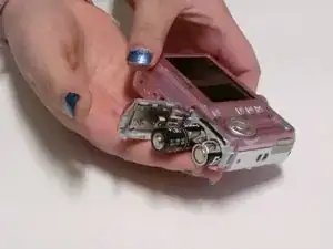
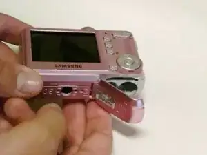
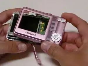
Carefully pull the back of the camera (the LCD screen side) away from the front.
-
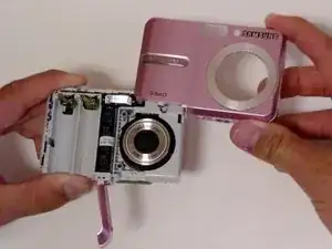
Turn the camera to the front (the flash side) and pull the case off.
-
There are clips on both sides of the case that secure it to the camera, so you may need to use a bit of force to remove the case.
-
-
-
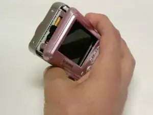
Orient the camera so the LCD screen is facing you.
-
Remove any tape holding the screen down.
-
Lift the LCD screen from the screen plate.
-
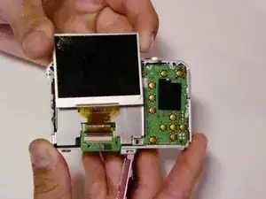
Lift the hinged lip on the camera body where the ribbon cable enters the connector.
-
Remove the ribbon from the logic board by gently pulling it straight out.
-
Try not to kink or crease the cable.
-
-
-
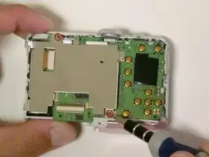
Using a #00 Philips screwdriver, remove the two 4.5 mm screws from the screen plate.
-
Separate the screen plate and logic board.
-
-
-
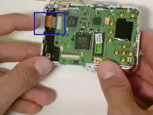
Locate the brown ribbon cable attached to the upper left edge of the logic board.
-
Remove this ribbon by gently pulling in the opposite direction of the logic board.
-
-
-
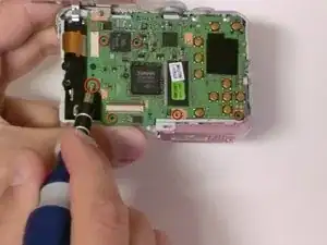
Using a #00 Philips screwdriver, remove the three 3.32 mm screws connecting the logic board to the camera.
-
Separate the logic board and the core of the camera.
-
-
-
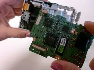
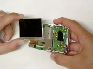
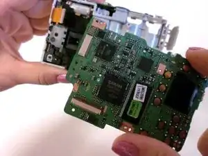
Separate the logic board by carefully pulling the logic board away from the camera.
-
Be careful not to damage the battery compartment. The battery sensors are attached to the logic board, so be gentle.
-
The USB connector is going to want to hang up on the housing, but once you have that free, the battery leads will slide out relatively easily.
-


To reassemble your device, follow these instructions in reverse order.