Introduction

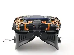
Prerequisite guide for removing the sensor array in the HTC Vive Pro 2 headset.

  1. HYe1UHPoxweusSWo
    HYe1UHPoxweusSWo
    Vp3EUnqHbUMB4IHc
    • Rotate the head strap forward as far as it will go.

  2. lGRGmrJqbaNo2Ngy
    lGRGmrJqbaNo2Ngy
    tWWbSxVKBHuNwFNq
    • Unplug the All-In-One Cable from your headset.

  3. HbQvVLZ6kJDOwNRY
    HbQvVLZ6kJDOwNRY
    gXqSBAhFSAFT2PXt
    2NxZbAVObNCtX5Cs
    • Remove the All-In-One Cable from the cable guides along the left side of the head strap.

    • During reassembly, connect the All-In-One Cable to the headset before routing it through the cable guides. This will ensure it has the right amount of slack.

  4. 3dG4uV5DpUAQZptQ
    3dG4uV5DpUAQZptQ
    YiMWeYhExTRMVKFO
    • Separate the top strap from itself where the Velcro secures it.

  5. VLPdIX14F6iiruXO
    VLPdIX14F6iiruXO
    UmwroeIuZueAKbbW
    e5EtHVxxujdCPHxB
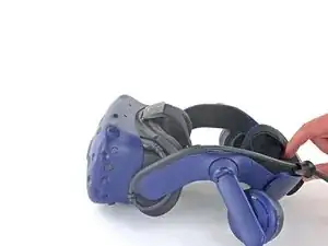
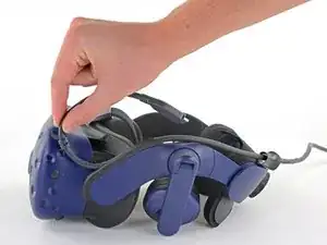
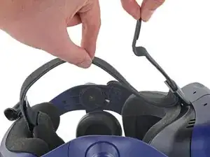
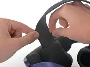
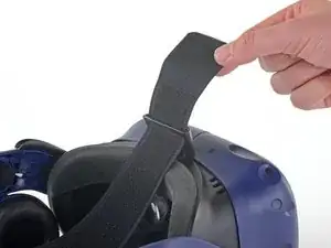
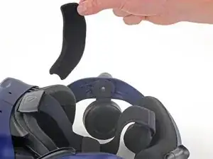
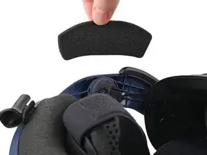
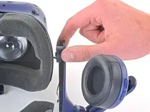
    • Peel back the Velcro securing the rear of the top strap.

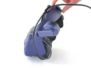
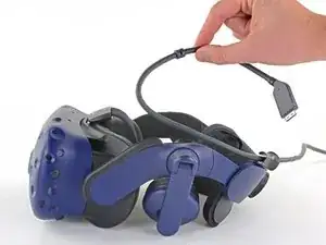
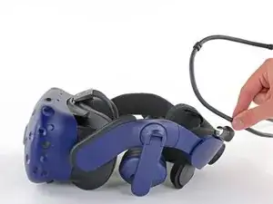
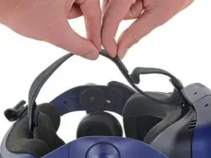
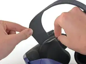
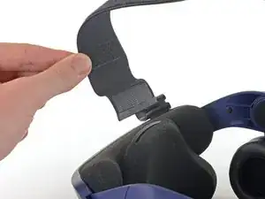
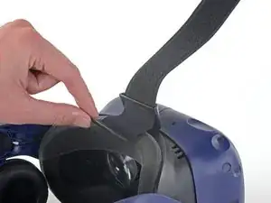
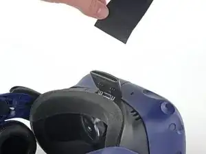
    • Feed the top strap out through the head strap to partially remove it.

  6. HcrR5RsAx4PE1h5j
    HcrR5RsAx4PE1h5j
    5vWrMBaqmgo4UBuT
    dCT1YqKf4opHuM2s
    • Feed the top strap through the clip near the front of headset to fully remove it.

  7. mPWInBOiUxUoIWHk
    mPWInBOiUxUoIWHk
    32lhPiKJihIMHrPC
    uLLL1T1UQArB36AA
    • Peel off both front side foam pads to uncover the speaker wires.

  8. slTfqZlYFlIpvRDn
    slTfqZlYFlIpvRDn
    v3IOaci2GtBbSDqL
    NSimWm3BecjdeNBf
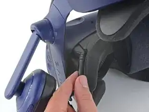
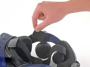
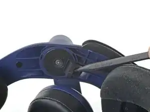
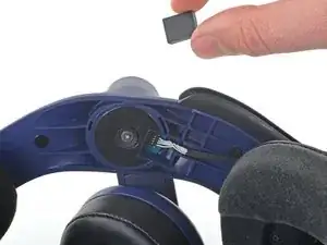
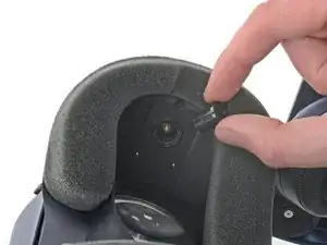
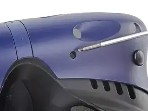
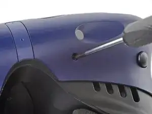
    • Use the point of your spudger to pry out the two rubber spacers next to the headphone screws.

    • Be careful not to accidentally pry any of the speaker wires under the rubber spacer.

  9. CVbX4PPWpfuB3Lev
    CVbX4PPWpfuB3Lev
    gTHLVQVxN2kPBLhD
    jNGX6DLIWu5LyFqO
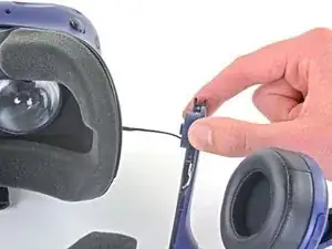
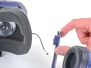
    • Use the point of your spudger to pry up and disconnect both the left and right headphone speaker wires.

  10. jyvLOIRiavsuSgk3
    jyvLOIRiavsuSgk3
    sAPbTeRiI1VYx2yZ
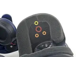
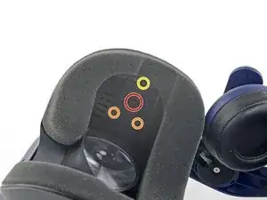
    • Use a T6 Torx screwdriver to remove the two 12.1 mm screws (one on each side) securing the head strap to the headset.

    • Use a T5 Torx screwdriver to remove the following screws securing the head strap to the headset:

    • Four 3.9 mm screws (two on each side)

    • Two 4.1 mm screws (one on each side)

    You do not need to remove the four 3.9mm screws or the 4.1mm screw. They do not secure the strap to the headset. You only need to remove the two 12.1mm screws.

    Ike -

  11. 2KDUshEaMsb6IDTc
    • Remove the two plastic spacers underneath the previously removed Torx T6 screw.

  12. wifnXFGOEgTEfFXd
    wifnXFGOEgTEfFXd
    JCVxpnXqUOImeZhg
    kcUiO6qBPPYHBAdT
    • Thread the headphone speaker wires out through both ends of the head strap.

  13. L5NuMAHXWiniFnKw
    L5NuMAHXWiniFnKw
    fchmXUSrgKuuexE4
    gcXlD1g3tInORGDc
    • The four screws securing the outer shell are covered with black stickers. If the stickers are difficult to remove, simply press your T6 Torx driver through them.

  14. sDPNRChUANGlsWVl
    sDPNRChUANGlsWVl
    nSWtSIcjKZNMcWXI
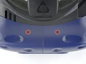
    • Use a T6 Torx screwdriver to remove the four 3.9 mm screws (two on top, two on bottom) securing the outer shell to the headset.

  15. uD3nCFq4UC1jAlOo
    uD3nCFq4UC1jAlOo
    eSKxLrCPpZkUIAwV
    cL5s4VLWZSnn2KeL
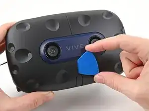
    • Insert an opening pick into the seam between the two halves of the outer shell.

    • Slide the opening pick through the seam to dislodge the clips securing it to the headset.

    • Only insert the opening pick as far as necessary. There are ribbon cables underneath the outer shell.

  16. OQ3pfEffTw4Ij5AV
    OQ3pfEffTw4Ij5AV
    qVMYL11EKF1VLFaE
    f3j2LaLZiBd5SQTF
    • Continue sliding the opening pick through each seam until all clips have been dislodged.

  17. JSbmxw1YSKMgdtPw
    JSbmxw1YSKMgdtPw
    CcrjxwRESCX1Zl4m
    tARXLBjquWncFS3u
    • Carefully slide each half of the outer shell off of the sensor array.

    • Be careful not to snag any of the ribbon cables underneath.

  18. YZWxVfrbYfiI1FkB
    YZWxVfrbYfiI1FkB
    mHCdtMGHnJelqe3y
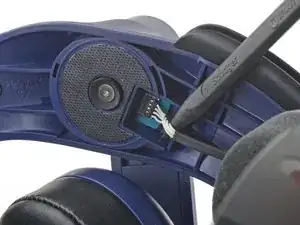
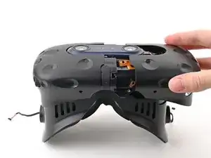
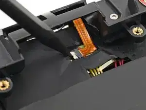
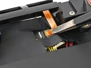
    • Use the point of your spudger, or a clean fingernail, to flip up the locking tab on the microphone ZIF connector on the daughterboard.

  19. tNolfMH62vTHhNWc
    tNolfMH62vTHhNWc
    wT6WXfygvplDTQKd
    • Use tweezers, or your fingers, to pull the microphone cable straight out of its socket.

  20. eHAxDYqV1ZniXKa4
    eHAxDYqV1ZniXKa4
    4Wtu4MOvXmG4FPNE
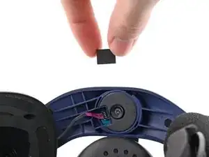
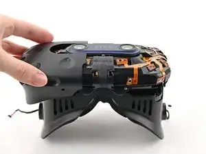
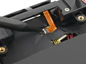
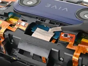
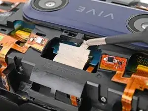
    • Use tweezers, or your fingers, to peel the conductive fabric off the sensor array ZIF connector on the motherboard.

  21. cwCFo3N2IaGTMSAj
    cwCFo3N2IaGTMSAj
    RkCvtrjuuHIHyWRq
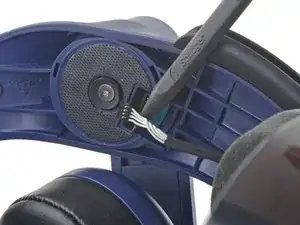
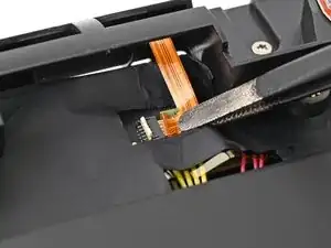
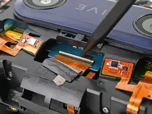
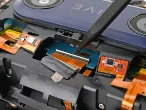
    • Use your spudger, or a clean fingernail, to flip up the locking tab on the sensor array ZIF connector.

  22. WDIZGVCc1XhCfu4c
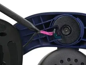
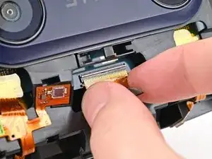
    • Use your fingers to grip the left and right sides of the sensor array cable and pull it straight out of its socket.

  23. tUEjReVw4a62NUCp
    tUEjReVw4a62NUCp
    UiIqDUoPfmYVTG1U
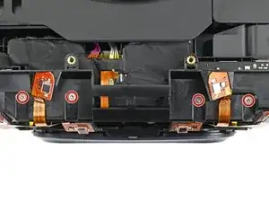
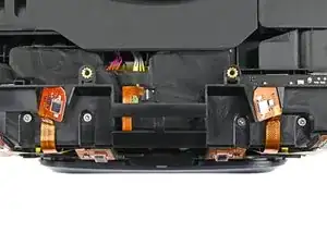
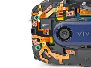
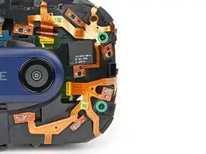
    • Use a T5 Torx screwdriver to remove the four 3.0 mm‑long screws securing the top of the sensor array.

  24. 1lsMw6lOqLMS4OR2
    1lsMw6lOqLMS4OR2
    lxK6jlvlgoT5PFRF
    bQbuEDAqpCgYiPHe
    • Use a T6 Torx screwdriver to remove the four 3.8 mm‑long screws securing the front of the sensor array.

  25. F3syMmxwrEoZgM3K
    F3syMmxwrEoZgM3K
    bUQHIYRLaTTveMUT
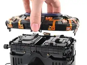
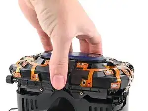
    • Lift the sensor array straight off the lens assembly and remove it, making sure you thread the cable through its slot.

    • During reassembly, make sure the sensor assembly cable is threaded through its slot before continuing.

Conclusion

To reassemble your device, follow these instructions in reverse order.

Alex Diaz-Kokaisl

Member since: 16/01/22

163004 Reputation

0 comments