Introduction

If your Whirlpool Duet Electric Dryer, model number WED9200SQ1 has not been working, it could be that the circuit board is malfunctioning and needs to be replaced. In this guide, we will walk you through the steps to replace the malfunctioning circuit board. The main board is an integral part of your dryer's electrical system, distributing power to various components for safe and efficient operation. Before attempting this repair, it is crucial to unplug your dryer to prevent electric shock. Utilize ESD-safe tools to protect the dryer's electronic components from static damage.

  1. mfkIicQH4JRbIZOp
    mfkIicQH4JRbIZOp
    Wk5w5QP6OQJlLghm
    fMlbWWQXRIFg31XY
    • Before attempting this repair, it is crucial to unplug your dryer to prevent electric shock.

    • Use a T5 Torx screwdriver to remove two 6.3 mm screws. from the top back of the dryer.

  2. NSK2MWeaKNCpeXLL
    NSK2MWeaKNCpeXLL
    fZXMYtk4WThanoZj
    sJvUb6DcWEA2c2IQ
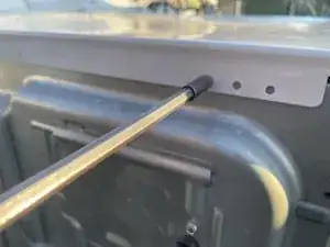
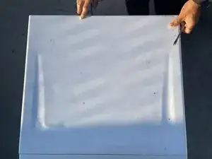
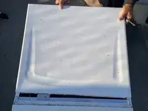
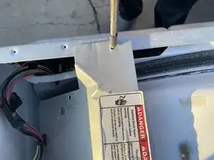
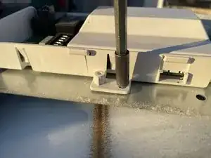
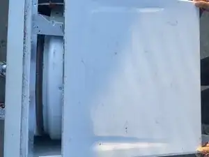
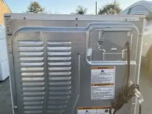
    • Slide the top of the dryer off to access the internal components.

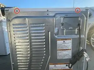
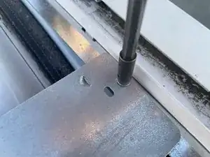
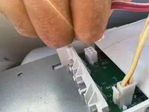
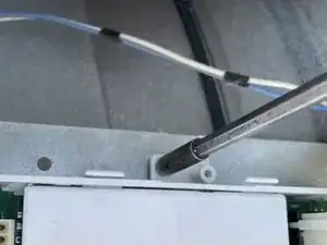
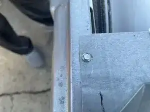
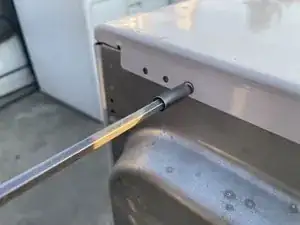
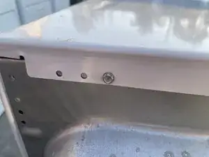
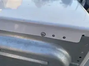
    • Use a T5 Torx screwdriver to remove two 6.3mm screws.

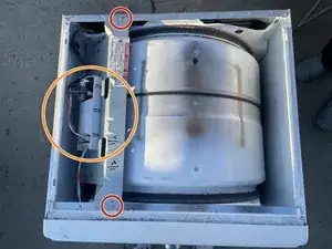
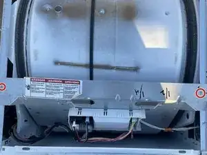
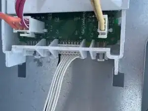
    • The circuit board is mounted on a metal rack..

  3. 6IwwHhIkHXiNhDGL
    6IwwHhIkHXiNhDGL
    eCC6SOYxmDDhEWZu
    yGeETdQYbVSCBfjQ
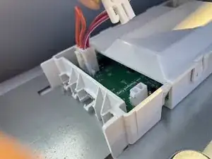
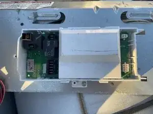
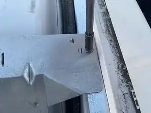
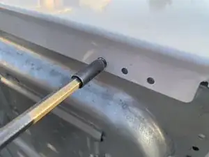
    • Use a T5 Torx screwdriver to remove the 6.3 mm screws on both ends of the metal shelve.

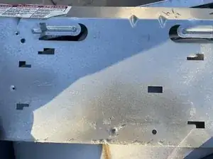
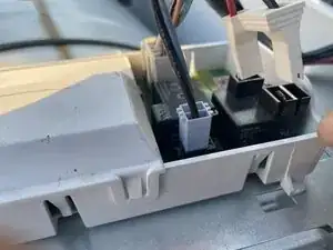
    • Slide the metal shelve out to access the main board.

  4. kmPIiU3Jn4kdWTML
    kmPIiU3Jn4kdWTML
    BLHjDHEkPuVVDIAd
    OrHPuOHDHOFYHE4a
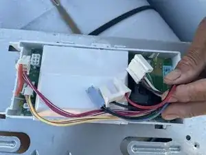
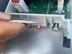
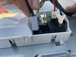
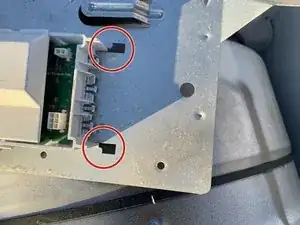
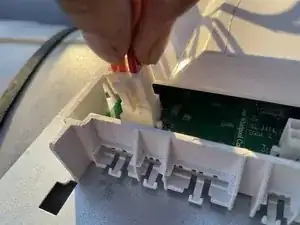
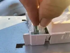
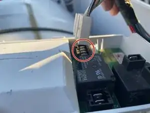
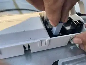
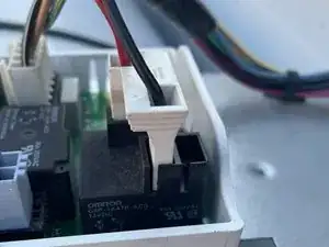
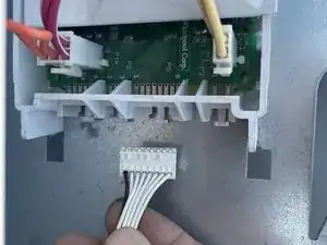
    • Remove all the circuit wires from the circuit board. Grab the circled wire to remove.

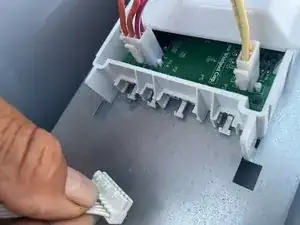
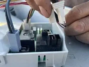
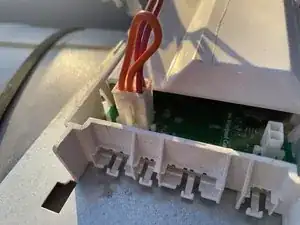
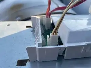
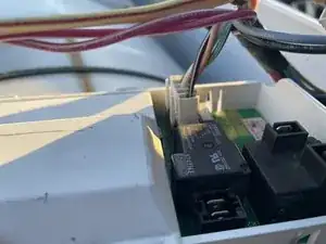
    • Remove the other wires.

    • Work at an angle with the metal mount still inside the dryer.

  5. msE1UDI55IlvW2gC
    msE1UDI55IlvW2gC
    JLajAAFUgUEHURFD
    wUZPLwt5nOYNYvYF
    • Keep removing the wires until every wire is disconnected from the old circuit.

  6. eIkWGZWFkIYJadDO
    • Once you've disconnected the wires, the wires should look like this in the image.

  7. tq1Ntr4jGDDFbgAG
    tq1Ntr4jGDDFbgAG
    sgLCSdAMOPliB6xF
    C4PZtVuGOGYDAuYL
    • Use a T5 Torx screwdriver to remove the 6.3mm screw.

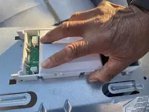
    • Use your hand to grab the old circuit and move it from the left to the right to get the circuit removed.

    • There should not be anything on the board.

  8. QPqLuMTCZfUUqWiX
    QPqLuMTCZfUUqWiX
    REbsiiGZIJREWamf
    PpOhGdBrQRqWTHZo
    • Use the new circuit to put in the board. Ensure the two white hooks are connected to the metal base.

    • Use the T5 Torx screwdriver to screw the 6.3mm screw to the new circuit attached to the metal board.

    • The new circuit shouold be tight to the metal

  9. O2tI6FTMLiJ2ePIu
    O2tI6FTMLiJ2ePIu
    CyMOXu4tPtXU6ZGQ
    cUqkSJsTehagnXIr
    • Attach the orange and red wires into the circuit.

    • Do to the same for the other wires

  10. RomRPONMjWxK6QZp
    RomRPONMjWxK6QZp
    uQLSpsDsRJohLvbP
    RtcmuEAiEiN2v3ml
    • Insert the red and white wires into the circuit.

  11. OYZZAdLTpmkSHEMH
    OYZZAdLTpmkSHEMH
    icAqfNCA6oLfOjLs
    MTWkYdFIaiZ5U2lQ
    • Refer to the image for where to insert the wires.

  12. q6muxKROnexPW5q5
    q6muxKROnexPW5q5
    TvtVvCBj4DWLOTFO
    • Attach the white wire to the circuit.

  13. itTIIwnoNUu4PWVP
    itTIIwnoNUu4PWVP
    bfYfKC1w4VqHweXc
    LQQdoO33YKBq4jRl
    • Use the T5 Torx screwdriver to screw the 6.3mm screw at both sides of the metal board.

  14. tCtTBQGcJUsexWJh
    tCtTBQGcJUsexWJh
    nMXFfVBrPBnBmP6i
    qOKFED5UgZqCNWFy
    • Reattach the top board

    • Use a T5 Torx screwdriver to screw the left 6.3mm screw into the top of the board

  15. rSocCUZjhbDkRBSu
    rSocCUZjhbDkRBSu
    Ka2PLQRDr6sUpWam
    wJYIIJgCIR1rodFL
    • Use a T5 Torx screwdriver to screw the 6.3mm screw on the right.

  16. e2HBtGODYuimh12N
    • Once you are done screwing the back, the dyer should be ready to use.

Conclusion

To reassemble your device, follow these instructions in reverse order.

Cesar Vazquez

Member since: 05/03/24

253 Reputation

0 comments