
Introduction
Your dryer is not starting and displays an F-01 fault? This guide will show how to repair in less than an hour and for under 30$.
This guide may also apply for other make/model using a similar control board.
Most of the time this failure is cause by a worn out motor relay, so this is what we are going to be replacing, along with the surge supressor and the heater relay. Basic soldering skill is then required for this fix. Otherwise the control board needs to be replaced at a +400$ cost.
Note that the original Omron relay found on my board are now obsolete, I used replacement relays with same specs and footprint (see parts).
Parts
-
-
Unplug the dryer from the wall outlet.
-
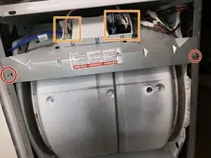
Remove the 2 screws securing the top panel.
-
Slide the top panel toward the back, then lift.
-
-
-
Unplug the wires from the control board
-
Remove the 2 screws securing the control board assembly.
-
Remove the screw to free the control board.
-
Press the notch underneath the control board assembly then slide toward the front to remove the control board.
-
-
-
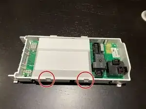
Lift the 2 tabs to remove the cover.
-
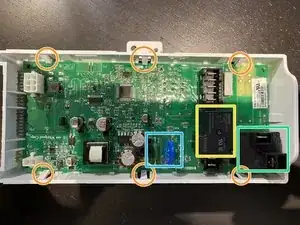
Press the 6 tabs and lift the board up to free it from the enclosure.
-
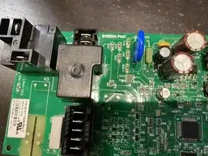
Motor relay.
-
Heating element relay.
-
Motor relay surge supressor.
-
-
-
Damage caused by heat generated by worn out relay contact.
-
Desolder and remove both relays, varistor and resistor.
-
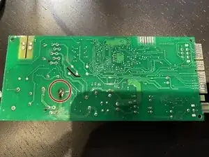
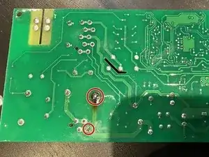
Board with components removed. Relay terminal is in bad shape and melted on the board.
-
Clean the damaged soldering pads on both sides before installing new components.
-
-
-
Install the new components.
-
Make sure there is good continuity between the 2 terminals and that the trace was not damaged by heat from the relay. If there is no continuity, add a good gage wire between the terminals as it carries the motor current.
-


To reassemble your device, follow these instructions in reverse order.
One comment
Great post, thank you... We live in an age of vast dissemination of information, making everyone an expert in everything. I am assuming there is a hall effect sensor to ensure the drum is rotating as after pressing start, there is an audible click for the motor relay closing and if the drum does not rotate, there is couple of second delay before the code is thrown. Clearly on my gas Duet this was arcing awhile at the relay solder because of the scorching on the plastic housing and pcb. I cleaned up the trace and post with a brass brush, dab of flux, soldered it back up, checked continuity and drying clothes again.