Introduction
The wheels are an important component of the vacuum that can easily get clogged or damaged and will render the vacuum unusable. If you need to replace the wheels of your Wyze WVCR200s robot vacuum, follow this guide.
Signs you have a bad wheel may include hearing a motor spinning when the robovac turns on. If you hear a motor running, quickly flip the vacuum over to see which wheel is spinning. This is likely the bad wheel that needs to be fixed or replaced.
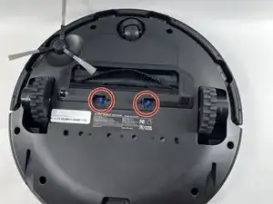
Also, when ordering replacement wheels, use this guide to order the correct wheel assembly. Flip the vacuum upside down so you can see the bottom. Orient the small wheel to the front. The RIGHT wheel is directly behind the corner brush. The left wheel is the other one, or on the left when looking at the vacuum in this orientation.
-
-
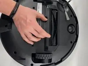
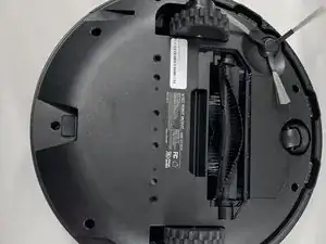
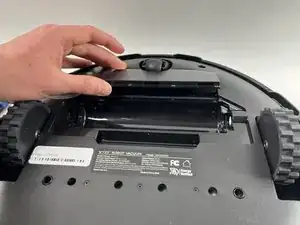
Pinch the blue tabs below the rotating brush towards each other.
-
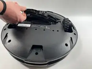
Lift the plastic housing surrounding the rotating brushing straight up, and the remove it from the vacuum.
-
-
-
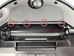
Use a screwdriver to remove four screws along the edge, just above where the brush was removed.
-
-
-
Lift the battery out from underneath the cover.
-
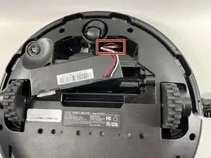
Carefully disconnect the battery from the vacuum port.
-
-
-
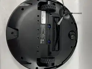
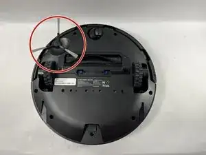
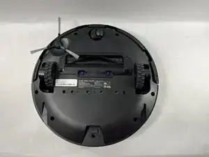
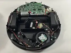
Flip the vacuum upside down so the underside of the device is facing up.
-
On the upper left of the device, you should see a spinning brush with three arms protruding out. This is the side brush.
-
-
-
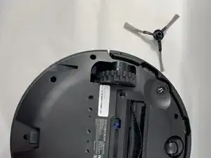
To remove, grab the three arms of the brush and pull upwards. The arms should be tight, but should not require too much force to lift off.
-
-
-
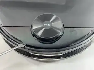
Use a spudger to pry the cover off that surrounds the vacuum mechanism.
-
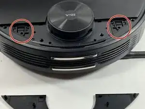
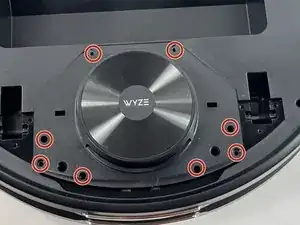
Remove the six screws securing the access cover hinges.
-
Remove the cover.
-
-
-
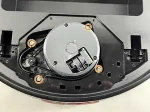
Use a screwdriver to remove the four screws surrounding the LIDAR sensor cover.
-
Use a screwdriver to remove the four screws holding the mechanism itself.
-
Lift the LIDAR sensor from the vacuum.
-
Disconnect the cable from the vacuum.
-
-
-
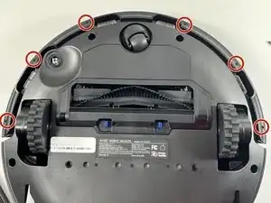
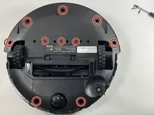
Use a screwdriver to remove the ten screws on the back side of the vacuum that hold the outer shell in place.
-
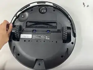
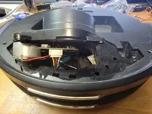
Use a spudger or opening tool to pry along the edges of the vacuum and separate the two parts.
-
-
-
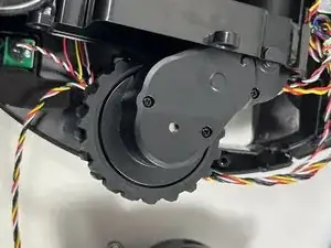
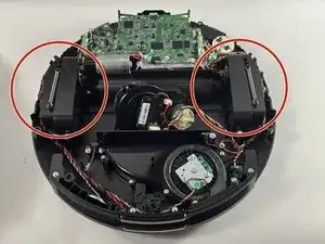
The wheels are located on each side of the vacuum.
-
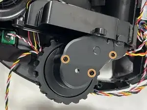
Use a screwdriver to remove three screws from each wheel holding them in place.
-
Remove the wheels.
-
-
-
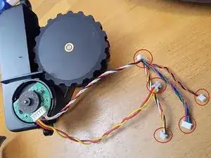
There are 5 connectors on a new wheel assembly, but the connectors vary a little for the left wheel assembly vs the right wheel assembly. These images are specific to the right wheel assembly. See the next step for the left wheel assembly images.
-
Locate the 5 connectors on the vacuum. Note the direction all plugs are plugged in so the connectors can be reconnected the same way.
-
-
-
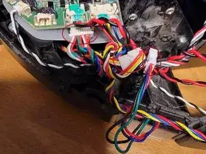
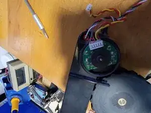
This is very similar to the right wheel assembly, but the connector locations are a bit different. MAKE NOTE of how the cables/wires are run around the wheel assembly. Failure to tuck the wires back into the same wire guides may result in issues getting the cover back on, or interference with the bumper switch and or wheel assembly.
-
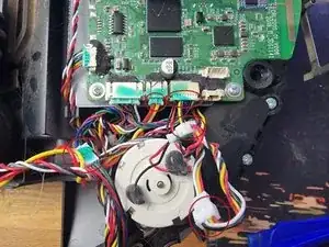
Locate the 5 connectors for the left wheel assembly. Note the direction for all plugs so the connectors can be reconnected the same way. See the images for the location of the plugs.
-
For the left wheel, two of the sockets for these plugs are under the motherboard. Two others are tucked under the motherboard, and the 5th connector goes to the bin sensor behind the wheel assembly.
-
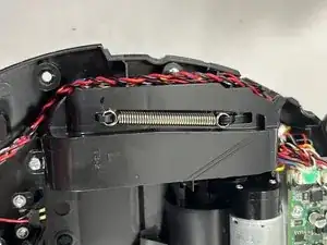
After replacing the wheel assembly, take your time to make sure all the wires are tucked in properly, and if there's a tie wrap around the cables to hold them out of the way of the bumper switch, replace the tie wrap with a new one.
-
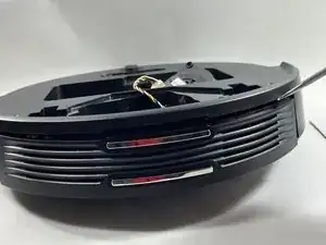
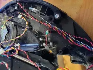
The last image shows a BAD left wheel assembly. Note how the white wire is severed from the plug on the wheel assembly.
-

To reassemble your device, follow these instructions in reverse order.