Introduction

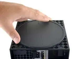
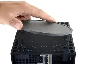
Use this guide to replace a faulty optical drive in an Xbox Series X (2TB Galaxy Black edition).

Before you begin, completely power down and unplug all cables from your console. Remember to follow general electrostatic discharge (ESD) safety procedures while repairing the console.

The board inside the optical drive is software-linked to the console’s motherboard. This board will need to be transferred into the replacement optical drive to restore full functionality. This will require you to de-solder and solder two wires. Follow general soldering safety guidelines such as wearing eye protection, working in a well-ventilated area, and washing your hands after with soap and water after soldering.

  1. RVl55HBQvdetmSvB
    RVl55HBQvdetmSvB
    bninbkWq1A3JUpAc
    KABeVTVxpkLJFcXx
    • Before you begin, completely power down and unplug all cables from your console.

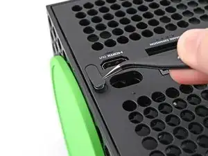
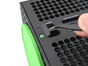
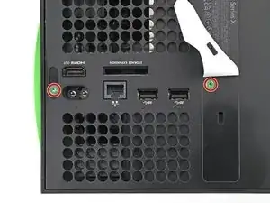
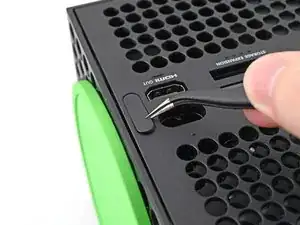
    • Use a pair of tweezers to remove the sticker hiding the first screw on the back panel, near the base.

  2. K4xhH6KyAKefxNPf
    K4xhH6KyAKefxNPf
    LKWeh2voLVCkB2S2
    BhSNKZqZoRyUagr3
    • For cleaner removal, use an iOpener or hair dryer to heat the sticker.

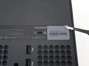
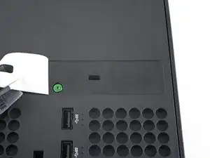
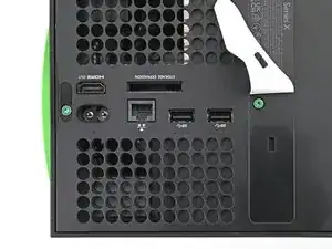
    • Use a pair of blunt tweezers to peel back the large sticker on the back panel to reveal the second screw.

    • You only need to peel this sticker to where you can access the hidden screw. You don't need to pull it completely off.

    • Technically, these are tamper-evident stickers, but don't worry—Microsoft can't legally void your warranty, as long as you don't damage anything. Have fun!

  3. JHlVtqMo2mYuLYqU
    JHlVtqMo2mYuLYqU
    DDJZMCrp4jdKibXp
    • Use a T8 Torx driver to remove the two 7.4 mm‑long screws securing the back panel.

    • Throughout this repair, keep track of each screw and make sure it goes back exactly where it came from to avoid damaging your console.

  4. H2vDPcDIVvSraKLb
    H2vDPcDIVvSraKLb
    Ci1N4TNyoUHgDbIL
    YgokPmUJA4dPS42A
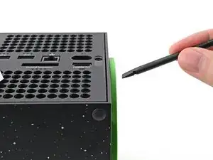
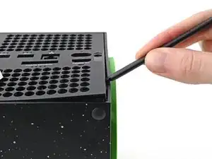
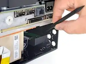
    • Insert the flat end of a spudger into the gap between the back panel and the shell, near the left side of the base.

    • Pry up the back panel to release it from the locking clips.

  5. 1MkWNRXA5UoF3xIg
    1MkWNRXA5UoF3xIg
    EhweH3oqCytMOFER
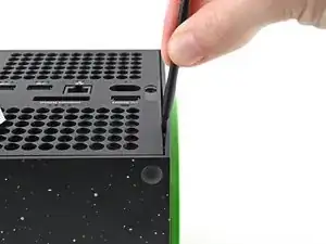
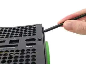
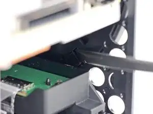
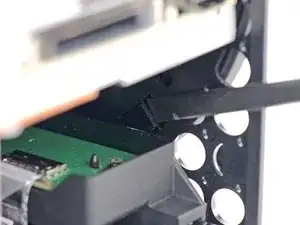
    • Insert the flat end of a spudger into the gap between the back panel and the shell, near the right side of the base.

    • Pry up the back panel to release it from the locking clips.

  6. VZLHaMniba2rLHWM
    VZLHaMniba2rLHWM
    XvF6R5ceStYjXxWJ
    TKgSJCCImCotgsQD
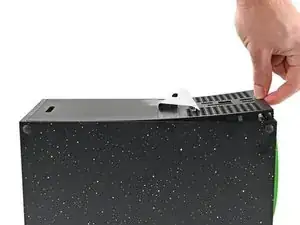
    • Grip the back panel at the opening you just created and pull it up and away from the shell to unclip the long edges.

    • During reassembly, press along the edges of the back panel to snap it into place.

  7. CGCSwKMAKnv3bArr
    CGCSwKMAKnv3bArr
    RFQ5eLxqPSIVrGAO
    SYnBeLFltCZPMuoM
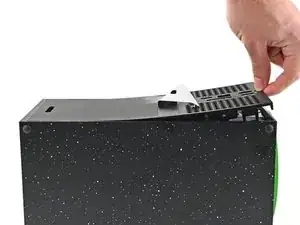
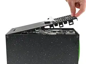
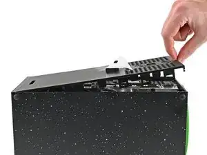
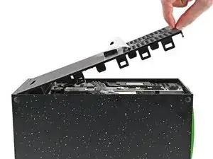
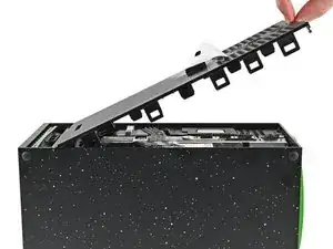
    • The back panel slots into a gap at the top of the shell.

    • Tilt the back panel up and pull it away from the top edge of the shell to release it from the gap.

    • Remove the back panel.

  8. TeS1w2jBIiJyJ5tC
    TeS1w2jBIiJyJ5tC
    GBcGsYAAuvqUAZFE
    MjvRJVRGOvIri4t6
    • Use the flat end of a spudger to lift up on the locking tab holding the base to the shell.

  9. N5ypbFiuFLLgCRbP
    N5ypbFiuFLLgCRbP
    SvsN3qWZdXACBrlc
    MfVUqOiHMbDUfFb5
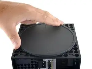
    • Grip the base and rotate it counterclockwise to unlock it from the shell.

    • You may need to hold the locking tab open while you get the base started.

    • Remove the base.

    • During reassembly, drop the base tabs into their holes on the shell and twist clockwise until the base snaps into the interior locking tab.

    • When locked in place, the "Hello from Seattle" line will be parallel with the device's sides.

    had trouble getting the base off, what worked for me is setting the console on the table sitting on the base and turning the whole console while pushing down.

    techy Waterville -

  10. WCybWp1L2MMPSGZ3
    WCybWp1L2MMPSGZ3
    re5IVejujiRDrS1l
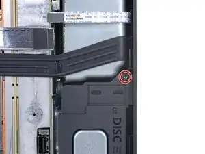
    • Use a T8 Torx driver to remove the two 8.8 mm screws securing the optical drive's vibration isolator to the shell: one on the base and one on the top of the isolator.

  11. Sv4TqfXBjJZ6SbRH
    Sv4TqfXBjJZ6SbRH
    KK1xoHxekFkfFF4m
    5rqMYEVtOxgVyGeJ
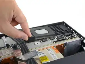
    • Lift up the optical drive's vibration isolator to remove it.

    • The vibration isolator grips the sides of the optical drive with silicone pads, so you may need to "walk" the isolator off of the drive to slip it off each side.

    • During reassembly, ensure the vibration isolator is pushed down and around both edges of the optical drive, so it sits flush with the rest of the center chassis.

  12. CuDAfMsFFYR4hvEI
    CuDAfMsFFYR4hvEI
    1ZM1OpOHMG6rvTHp
    6nmdPY3SVdBaAHVU
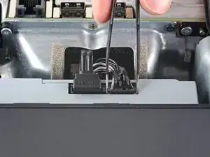
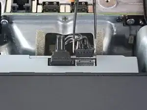
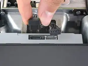
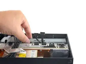
    • Use a pair of blunt tweezers to grip the edges of the optical drive power connector and pull up to disconnect it from the optical drive.

    • Always pull cables by their connectors and not the wires themselves.

    • Use your fingers to pull up and disconnect the data cable from the optical drive.

    Once again, DO NOT use tweezers to pull these connectors out. That’s a great way to slip and damage something.

    Leif DeWolf -

    I managed to get the power connector unplugged, but the data cable just refuses to move. I've used quite a bit of force, and using any more feels like I would damage it. I have no clue on how to get it out safely :(

    Izaac Brånn -

    Try to "walk" the connector out: pry up one side, then the other. Best of luck!

    Carsten Frauenheim -

  13. wM13ZRag2JLuhebq
    wM13ZRag2JLuhebq
    aHGUfCTjqFMty3f2
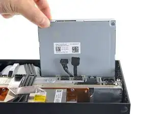
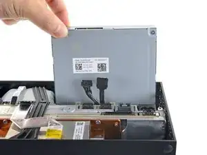
    • Grip the top edge of the optical drive and pull it out of its slot in the shell to remove it.

    • During reassembly, align the pegs on the bottom edge of the optical drive with the guide holes on the bottom of the shell.

    • If the drive is misaligned, the top vibration isolator will not be able to be installed correctly, and the disc reader will be misaligned with the front of the console.

  14. cFxVgG2N3ViLFtvU
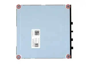
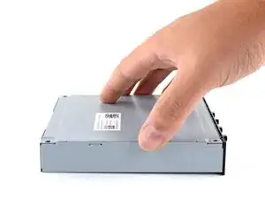
    • Use a Phillips screwdriver to remove the four 3.6 mm screws securing the optical drive cover.

  15. KVDUrCv5pM6xMJcM
    KVDUrCv5pM6xMJcM
    YGnbosEnvtkt2sH5
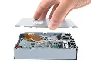
    • Lift the optical drive cover straight up to remove it.

  16. ffyr1hLIDBSWWeXV
    ffyr1hLIDBSWWeXV
    lboP4XKwNFPaZ4QV
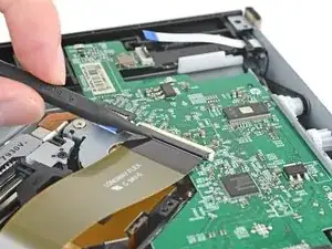
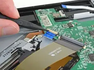
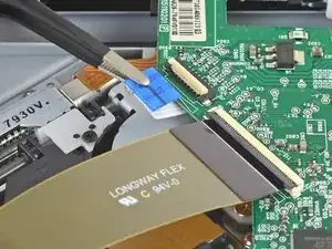
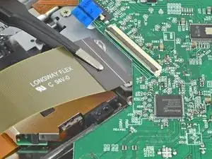
    • Use the pointed end of a spudger to flip up the hinged locking tab on the large ribbon cable's ZIF connector.

  17. 2UWOZSdUy4GRfxkA
    2UWOZSdUy4GRfxkA
    trIWjVfUgyJbABeB
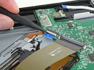
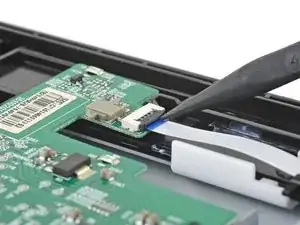
    • Use the pointed end of a spudger to flip up the hinged locking tab on the small ribbon cable's ZIF connector.

  18. BaDDhSo2vGAyHpUu
    BaDDhSo2vGAyHpUu
    DOCmQsLXI6OplPMZ
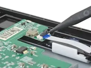
    • Use the pointed end of a spudger to flip up the hinged locking tab on the small ribbon cable's ZIF connector, near the corner of the optical drive.

  19. JgdTHtbUVTt6YASP
    JgdTHtbUVTt6YASP
    BSQOkb13rHiJyjKj
    GxBq4XhvvwRWExLR
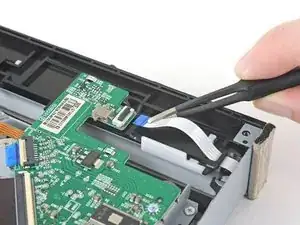
    • Use a pair of blunt tweezers to remove each of the three ribbon cables from their connectors.

    • Always pull ribbon cables straight out of their connectors, in the direction of the cable.

  20. y4dkwOBPLHu4c5w6
    y4dkwOBPLHu4c5w6
    NYQXKJSR2Oltyhn6
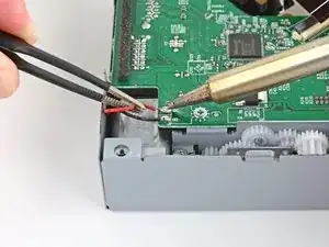
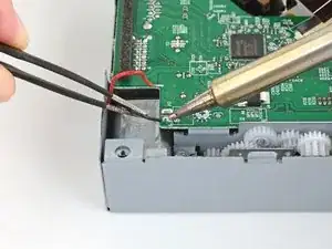
    • Use a soldering iron to desolder the red wire in the corner of the optical drive board.

    • Then, desolder the adjacent black wire. Use a pair of blunt tweezers to hold and pull away the wires from the board.

    • Follow general soldering safety guidelines such as wearing eye protection, working in a well-ventilated area, and washing your hands with soap and water after soldering.

    • Excessive heat may damage electrical components. Don't apply the soldering iron to the board for long periods of time.

    • When you install the original board into the replacement optical drive, solder the red wire to the solder pad labeled R. Solder the black wire to the solder pad labeled B.

  21. RlqQpWBRE5qNbFMH
    RlqQpWBRE5qNbFMH
    NBcfBPWZllILDpiY
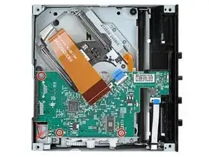
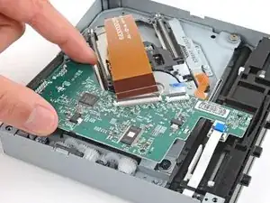
    • Use a Phillips screwdriver to remove the three 3.3 mm‑long screws securing the optical drive board.

  22. ZIh6WUYLOvtuRrVD
    ZIh6WUYLOvtuRrVD
    DMiomrVUu2OhSrCI
    IuBJY5LILIlUhFml
  23. NnOMPFF3AfiTNlyk
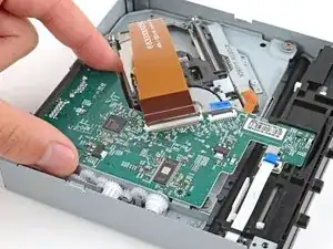
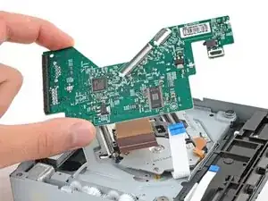
    • Remove the optical drive board.

    • Use the same process (starting at this step) to remove the optical drive board from your replacement drive.

    • You'll need to transfer your original optical drive board into the new drive.

Conclusion

To reassemble your device, follow these instructions in reverse order.

Take your e-waste to an R2 or e-Stewards certified recycler.

Repair didn’t go as planned? Try some basic troubleshooting, or ask our Xbox Series X Answers community for help.
Spencer Day

Member since: 14/09/22

95592 Reputation

0 comments