Introduction

Use this guide to replace the southbridge board on an Xbox Series X (2TB Galaxy Black edition).

Before you begin, completely power down and unplug all cables from your console. Remember to follow general electrostatic discharge (ESD) safety procedures while repairing the console.

  1. RVl55HBQvdetmSvB
    RVl55HBQvdetmSvB
    bninbkWq1A3JUpAc
    KABeVTVxpkLJFcXx
    • Before you begin, completely power down and unplug all cables from your console.

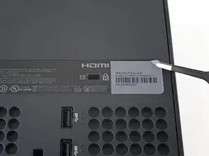
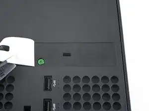
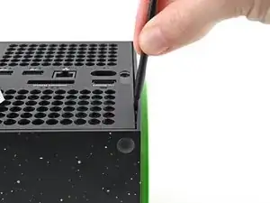
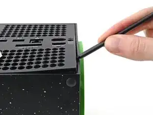
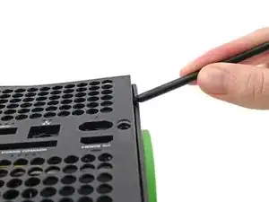
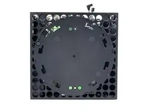
    • Use a pair of tweezers to remove the sticker hiding the first screw on the back panel, near the base.

  2. K4xhH6KyAKefxNPf
    K4xhH6KyAKefxNPf
    LKWeh2voLVCkB2S2
    BhSNKZqZoRyUagr3
    • For cleaner removal, use an iOpener or hair dryer to heat the sticker.

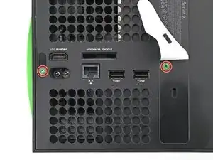
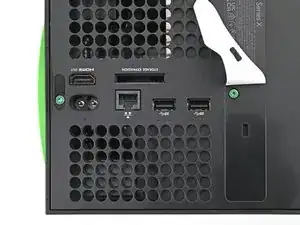
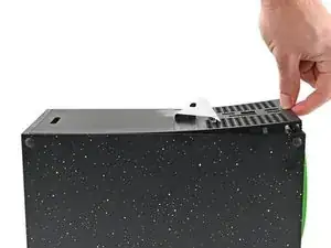
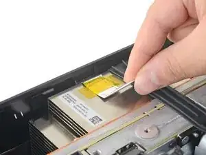
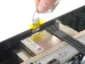
    • Use a pair of blunt tweezers to peel back the large sticker on the back panel to reveal the second screw.

    • You only need to peel this sticker to where you can access the hidden screw. You don't need to pull it completely off.

    • Technically, these are tamper-evident stickers, but don't worry—Microsoft can't legally void your warranty, as long as you don't damage anything. Have fun!

  3. JHlVtqMo2mYuLYqU
    JHlVtqMo2mYuLYqU
    DDJZMCrp4jdKibXp
    • Use a T8 Torx driver to remove the two 7.4 mm‑long screws securing the back panel.

    • Throughout this repair, keep track of each screw and make sure it goes back exactly where it came from to avoid damaging your console.

  4. H2vDPcDIVvSraKLb
    H2vDPcDIVvSraKLb
    Ci1N4TNyoUHgDbIL
    YgokPmUJA4dPS42A
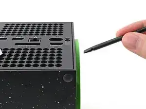
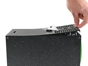
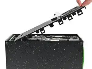
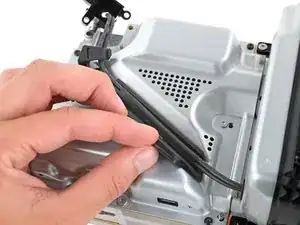
    • Insert the flat end of a spudger into the gap between the back panel and the shell, near the left side of the base.

    • Pry up the back panel to release it from the locking clips.

  5. 1MkWNRXA5UoF3xIg
    1MkWNRXA5UoF3xIg
    EhweH3oqCytMOFER
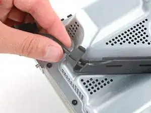
    • Insert the flat end of a spudger into the gap between the back panel and the shell, near the right side of the base.

    • Pry up the back panel to release it from the locking clips.

  6. VZLHaMniba2rLHWM
    VZLHaMniba2rLHWM
    XvF6R5ceStYjXxWJ
    TKgSJCCImCotgsQD
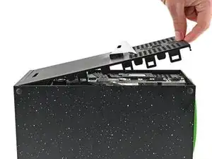
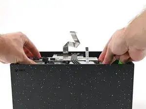
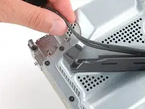
    • Grip the back panel at the opening you just created and pull it up and away from the shell to unclip the long edges.

    • During reassembly, press along the edges of the back panel to snap it into place.

  7. CGCSwKMAKnv3bArr
    CGCSwKMAKnv3bArr
    RFQ5eLxqPSIVrGAO
    SYnBeLFltCZPMuoM
    • The back panel slots into a gap at the top of the shell.

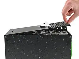
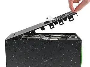
    • Tilt the back panel up and pull it away from the top edge of the shell to release it from the gap.

    • Remove the back panel.

  8. s5HXWZ15bUqFvXiV
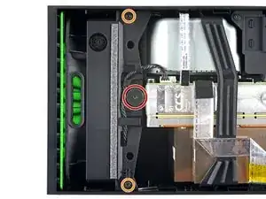
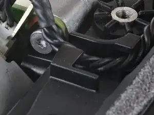
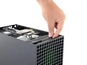
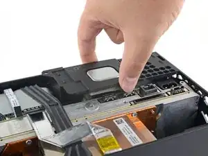
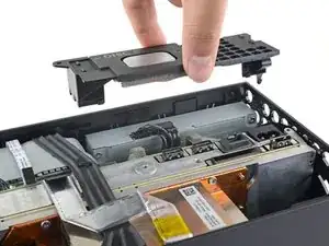
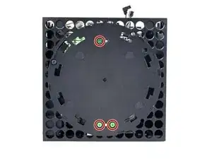
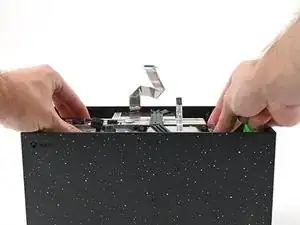
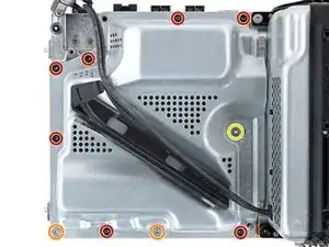
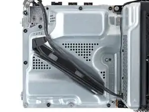
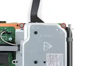
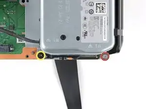
    • Use a T8 Torx driver to remove the three screws securing the fan to the center chassis:

    • One 10.5 mm pancake screw

    • Two 8.8 mm screws

    are there any 10.5mm wide head screw for the xbox fan for sale because i need a replacement because i accidentally broke mine

    GhostMindX9 -

    If the 10.5 mm screw isn’t budging, use some pliers to loosen it

    Joseph Grant -

  9. IPQZ2JOW6g3mq6yw
    IPQZ2JOW6g3mq6yw
    dDipWLCFPsWOO3Qq
    s5TfshEoqJTMEWXb
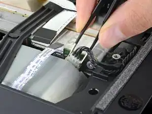
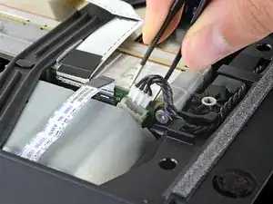
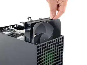
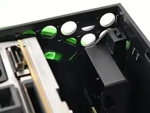
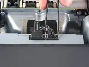
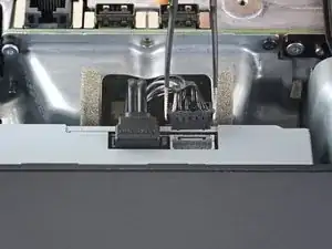
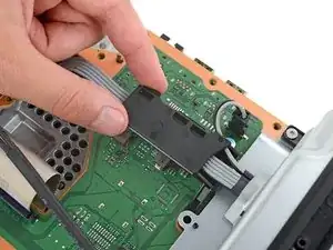
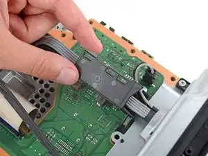
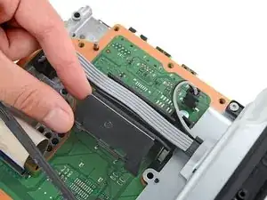
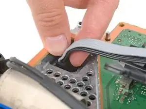
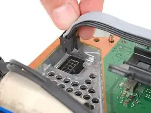
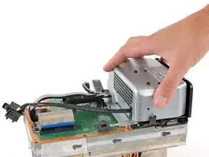
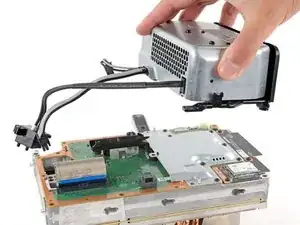
    • Use your fingers or a pair of blunt tweezers to grip the edges of the fan cable connector, and pull up to disconnect it from the center chassis.

    • Always pull cables by their connectors and not the wires themselves.

    • During reassembly, route the fan cable underneath its small cable guide on the fan housing so it doesn't interfere with the back panel.

    But don’t pull the connectors with tweezers because you will inevitably still damage the cable as you have no grip on the connector and the tweezers will slip.

    Leif DeWolf -

  10. 32I1KI24pY3JZu4k
    32I1KI24pY3JZu4k
    LWIG3ECKkFoVTfRt
    • Slide the fan out of its slot to remove it.

    • During reinstallation, note that the fan can only be installed one way—make sure Master Chief is facing you.

    • If you're replacing the fan, a new fan might not include the plastic installation bracket, which is attached to the fan with four T10 Torx screws. This isn't pictured in this guide.

  11. 1gRWbLYdvQVNLglV
    1gRWbLYdvQVNLglV
    siFvA31QIAGoCBVU
    • Use the flat end of a spudger to lift up on the locking tab holding the base to the shell.

  12. H61gQCXhAeEwiTCL
    H61gQCXhAeEwiTCL
    vpKvYYqcBSRlaRh3
    cNSKqxSIiBeq2f2M
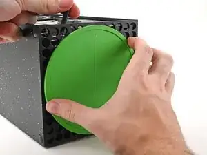
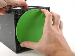
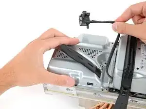
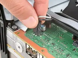
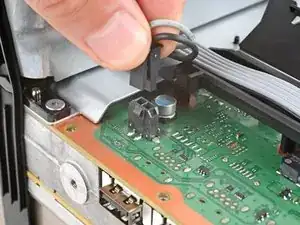
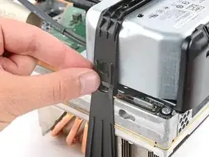
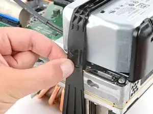
    • With the locking tab held open, grip the base and rotate it counterclockwise to unlock it from the shell.

    • Remove the base.

    • During reassembly, put the base tabs into their holes on the shell and twist clockwise until the base snaps into the interior locking tab.

    • When locked in place, the "Hello from Seattle" line will be parallel with the device's sides.

  13. WCybWp1L2MMPSGZ3
    WCybWp1L2MMPSGZ3
    re5IVejujiRDrS1l
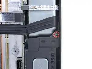
    • Use a T8 Torx driver to remove the two 8.8 mm screws securing the optical drive's vibration isolator to the shell: one on the base and one on the top of the isolator.

  14. Sv4TqfXBjJZ6SbRH
    Sv4TqfXBjJZ6SbRH
    KK1xoHxekFkfFF4m
    5rqMYEVtOxgVyGeJ
    • Lift up the optical drive's vibration isolator to remove it.

    • The vibration isolator grips the sides of the optical drive with silicone pads, so you may need to "walk" the isolator off of the drive to slip it off each side.

    • During reassembly, ensure the vibration isolator is pushed down and around both edges of the optical drive, so it sits flush with the rest of the center chassis.

  15. CuDAfMsFFYR4hvEI
    CuDAfMsFFYR4hvEI
    1ZM1OpOHMG6rvTHp
    6nmdPY3SVdBaAHVU
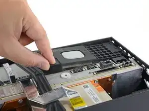
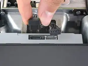
    • Use a pair of blunt tweezers to grip the edges of the optical drive power connector and pull up to disconnect it from the optical drive.

    • Always pull cables by their connectors and not the wires themselves.

    • Use your fingers to pull up and disconnect the data cable from the optical drive.

  16. wM13ZRag2JLuhebq
    wM13ZRag2JLuhebq
    aHGUfCTjqFMty3f2
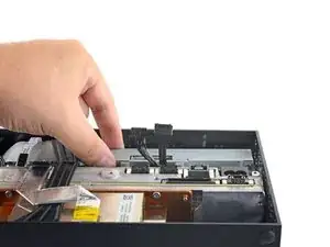
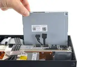
    • Grip the top edge of the optical drive and pull it out of its slot in the shell to remove it.

    • During reassembly, align the pegs on the bottom edge of the optical drive with the guide holes on the bottom of the shell.

    • If the drive is misaligned, the top vibration isolator will not be able to be installed correctly, and the disc reader will be misaligned with the front of the console.

  17. JmfLUPAhK4iPoKta
    JmfLUPAhK4iPoKta
    jKXjxBr3PUJCN2IC
    ByEIr6FVTymkUBqR
    • The ribbon cables and their connectors are extremely fragile, so always open locking tabs gently and pull cables slowly.

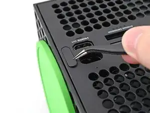
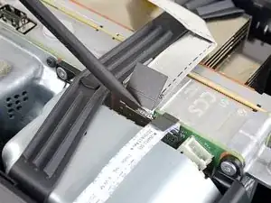
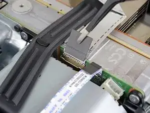
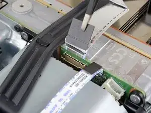
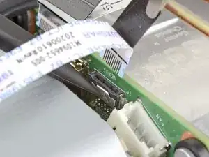
    • Use the flat end of a spudger to flip open the metal locking tab on the USB port ribbon cable.

    • During reassembly, gently snap the metal locking tab back into place once the cable has been inserted.

  18. HRTyZSjqcARt2QUf
    HRTyZSjqcARt2QUf
    j3q6cTvQGhhOFh4P
    • Use a pair of tweezers to pull up on the black plastic pull tab to disconnect the USB port cable.

    • Pull only on the pull tab, not the cable itself.

    • If the USB port cable feels adhered to the metal chassis, use an apply an iOpener or hair dryer to heat the cable. Depending on your model of Xbox, you may also need to slide an opening pick under the cable to separate the adhesive.

  19. aWlR2xiWMgjfsOTF
    aWlR2xiWMgjfsOTF
    eYfV56C23IVpqMKH
    qJ6KbLXg6weG2HPT
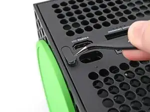
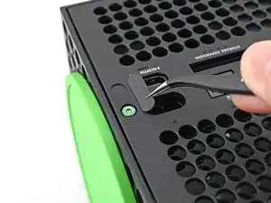
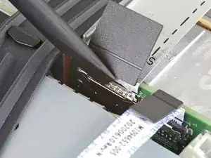
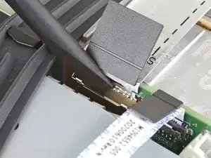
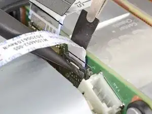
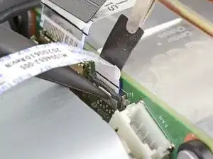
    • Use the pointed end of a spudger to depress the metal tab on the side of the power button cable's board connector.

    • With the metal tab depressed, use a pair of tweezers to pull up on the pull tab to disconnect the power button cable from the center chassis.

    • Pull only on the pull tab, not the cable itself.

    • Don't pull on the cable without depressing the metal tab, otherwise you risk damaging either the cable or the connector.

    • During reassembly, the cable should lightly "snap" into place when inserted.

  20. LgHlGlnOQJKOZPUm
    LgHlGlnOQJKOZPUm
    c1BPYLSZCmRomSpc
    • Use a T8 Torx driver to remove the three 7.4 mm screws securing the center chassis assembly to the shell.

  21. 2SOxZvDpDAsEMUQc
    2SOxZvDpDAsEMUQc
    CTkfVfWbW1Y1EVtT
    • Gently peel the taped USB port ribbon cable off of the heatsink.

    • Depending on your model of Xbox, the adhesive may be on the underside of the cable. If so, use an iOpener or hair dryer to heat the cable.

  22. NUPq1y3v3HJLA12r
    NUPq1y3v3HJLA12r
    F6TSUmaPYUqVjQFV
    htXFIk6ExYg4Z5vq
    • The center chassis assembly is aligned to the bottom of the shell with guide pegs. These pegs will need to slide out of their slots to allow the chassis to be lifted out.

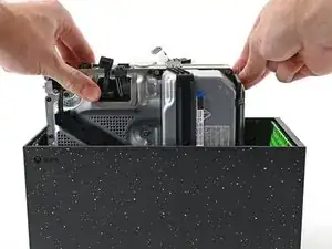
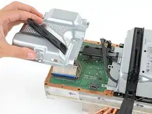
    • Grip the chassis and pull it towards the top of the shell, uncoupling the guide pegs from the shell.

    • Use two hands to lift out the chassis to remove it from the shell.

    • During reassembly, make sure neither of the ribbon cables get pinched as you lower the center chassis into the shell.

  23. JEAp2uQcBIxWjprO
    JEAp2uQcBIxWjprO
    JuJdGVbuSIsDtcve
    • Gently place the chassis heatsink-side down on a clean work surface.

    • During reassembly, this is a good point to clean the heatsink fins of any dust, dirt, or debris that may have built up over time. Use a dust blower or compressed air to clear out the fins.

  24. bCZlVYbCeYWLNPO2
    bCZlVYbCeYWLNPO2
    kfqk4xAQRFf3WC4j
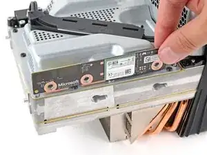
    • Use a T8 Torx driver to remove the three 9.6 mm‑long screws securing the antenna board to the center chassis.

  25. TbTnEVunHMgXVtjx
    TbTnEVunHMgXVtjx
    aXOggJBCMXbrCNkG
    QjLFK6kKIELBRB2b
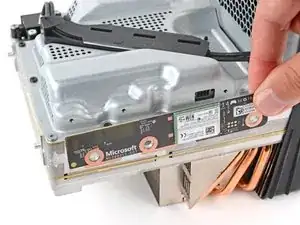
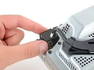
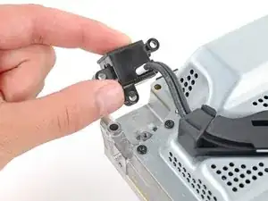
    • Grip the top right corner of the antenna board and pull it directly away from the center chassis to disconnect it.

    • During reassembly, align the board's connector with the port on the center chassis and press to reconnect.

  26. KrZfXIlegalLQXyn
    KrZfXIlegalLQXyn
    chkBWKxwllEUUWjo
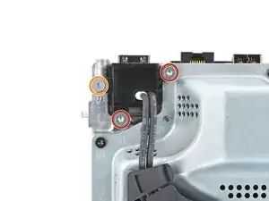
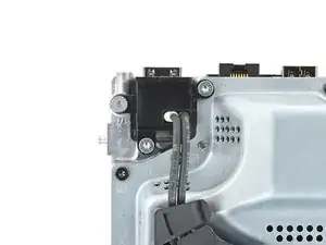
    • Use a T8 Torx driver to remove the three screws securing the power cable port to the chassis:

    • Two 13.1 mm‑long screws

    • One 35 mm‑long screw

  27. eRwtodYRaX5SFkfW
    eRwtodYRaX5SFkfW
    MFnfRXMWAHmWQsBZ
    • Lift the power connector out of its recess in the chassis.

  28. I2ADIyVhLoi2H1Ss
    I2ADIyVhLoi2H1Ss
    Ud2YtfstA3MWGiAI
    • Unlatch and open the lid on the power cable's plastic guide.

  29. s2jx6QE5UZVqCnu6
    s2jx6QE5UZVqCnu6
    y2jVnvSFTRZpPIoQ
    • Lift the power cable out from underneath the extra section of the cable guide.

  30. kdVNQWjXWQeNxtT6
    kdVNQWjXWQeNxtT6
    TJQAUdAyqmDvBbKX
    • Use a T8 Torx driver to remove the ten screws securing the board shield:

    • Seven 8.7 mm‑long screws

    • Two 35 mm‑long screws

    • These screws are very tight and may take significant force to loosen.

    • One 13 mm‑long screw

  31. yqHbnGMZjC6auQF3
    yqHbnGMZjC6auQF3
    qeGZEiixDEY2U1LJ
    QIBDSiDUcVF1BKwD
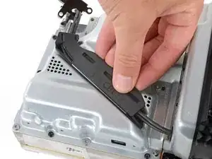
    • Hold the power supply cable out of the way and lift the board shield straight up to remove it.

  32. CKxZt4kXBkJVja12
    CKxZt4kXBkJVja12
    Sut11i5MCweZRkNG
    yE5XOIl2g3wJ646W
    • Open the lid on the power supply's plastic cable guide.

  33. GC1knsWOpf4FiRFc
    GC1knsWOpf4FiRFc
    yC2iGmxvd1RbYo2S
    CUcfygYFyCCIKjsv
    • Always pull cables by their connectors and not the wires themselves.

    • Use your fingers to pinch the power supply's two‑pin power connector, so the locking tab opens outward.

    • With the locking tab open, lift the connector straight up and out of its socket.

  34. eHQAVteodTBH4ULh
    eHQAVteodTBH4ULh
    iYrFuubURkHaCgKQ
    BAcwMqIZAEhSNmbe
    • Repeat the previous step to disconnect the power supply's 10‑pin connector.

  35. bwQbI4LJcIMWp5dh
    bwQbI4LJcIMWp5dh
    uASBpjekAyY3KNYu
    bIVfeGYVmYtSRCxG
    • Pull the end of the rubber strap down and away from the chassis to unlatch it.

  36. Uy3C6ldkpPFQ53XW
    Uy3C6ldkpPFQ53XW
    PFA23lflMpOhk1nL
    JCQft2vVc4BYROJn
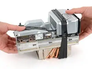
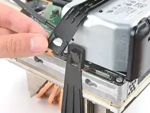
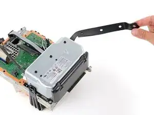
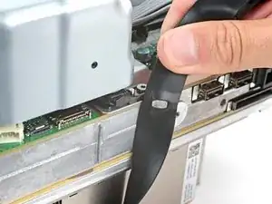
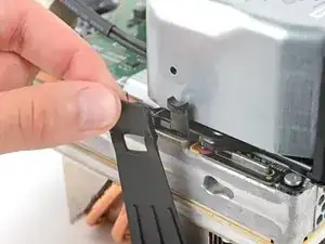
    • Pull the chassis strap off its three alignment posts and unlatch it from the sides of the power supply.

    • You can leave the strap under the chassis or remove it.

    • During reassembly, make sure the nubs in the middle of the strap go unto their cutouts on the heat sink fins.

  37. aIHnxLoR4jMfIY5C
    aIHnxLoR4jMfIY5C
    6FUVvTNQQdqY5vt3
    • Use a T8 Torx driver to remove the four screws securing the corners of the power supply:

    • Three 35 mm‑long silver screws

    • One 8.7 mm‑long black screw

  38. MqVOhdQvxBDEMIGq
    MqVOhdQvxBDEMIGq
    hVQVRUfAs5nKuq5X
    • Lift the power supply straight up and remove it.

  39. q3QlHpvH1BXGCxSR
    q3QlHpvH1BXGCxSR
    1yRcfe2obeUQZagC
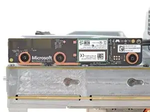
    • Use a T8 Torx driver to remove the three 8.7 mm‑long screws securing the Wi-Fi antenna board.

  40. sRJjUKaHdApFlTXH
    sRJjUKaHdApFlTXH
    4RgZdNCudHDjkfeV
    bxccoepqqUSuxCdf
    • Don't pull up on the antenna board until it's completely disconnected.

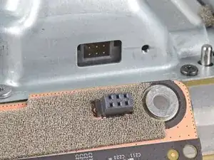
    • Grip the antenna board and pull it directly away from the center chassis to disconnect it.

    • Remove the antenna board.

    • During reassembly, align the board's connector with the port on the center chassis and press to reconnect.

  41. vQbGPQAFYiEJlna2
    vQbGPQAFYiEJlna2
    OtMbXiFJiEqYhF4M
    UE4eZYfC5QNdR35X
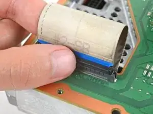
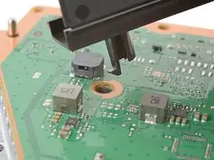
    • Use your fingers to pinch the locking tab in the center of the interconnect cable connector.

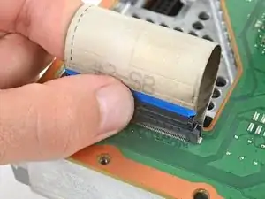
    • While pinching the tab, insert the flat end of a spudger between the top of the socket and the connector's tab.

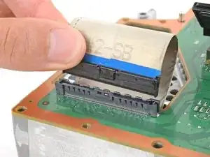
    • Twist the spudger to lift the connector out of its socket until the clip in the center disengages.

  42. MFnQHICLwwGnFpl5
    MFnQHICLwwGnFpl5
    V4Wo65FvFiYLM6qM
    • Use your fingers to pull the connector straight up and out of its socket.

    • During reassembly, insert the interconnect cable connector into its socket and press down on both edges until the connector snaps into place.

  43. AkRy3lmXR2KORYGN
    AkRy3lmXR2KORYGN
    MJ1rJmEuHgHDMMct
    HF5jnHZIuWvOpPPR
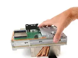
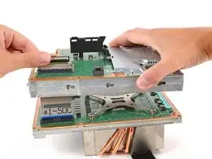
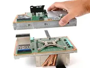
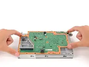
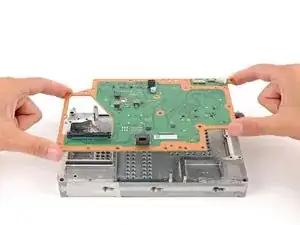
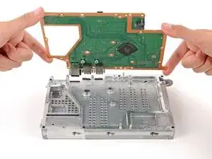
    • Lift the center chassis off the motherboard and heatsink assembly, routing the interconnect cable through its cutout.

  44. YYdJojUBfHZPvjmx
    YYdJojUBfHZPvjmx
    XoQw2TQuKQmpFYNQ
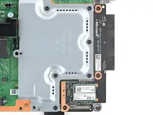
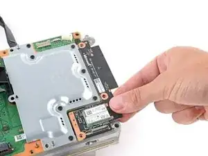
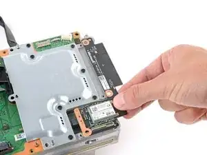
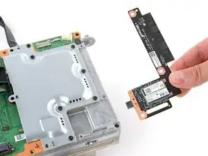
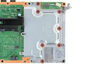
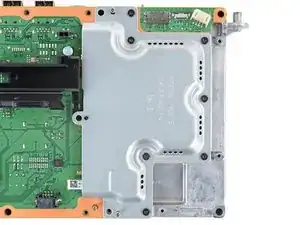
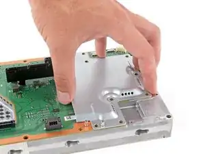
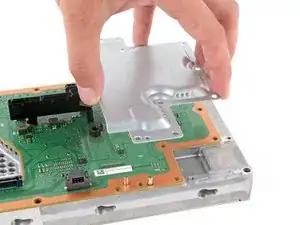
    • Use a T8 Torx driver to remove the seven 8.7 mm‑long screws securing the southbridge board shield.

  45. cJKsCDMh1RpNkGL6
    cJKsCDMh1RpNkGL6
    AFWmjIYDVmfOpDle
    • Remove the board shield.

  46. bUWoylqXeaJtJuki
    bUWoylqXeaJtJuki
    HFrXT3OQO3vSwO3a
    hfpykEGX6YidDBYA
    • Lift up to remove the power supply cable guide from the southbridge board.

    • During reassembly, insert the post with a tab into its screw hole first before aligning the rest of the cable guide.

  47. w42Twy2VkgZKjNAW
    w42Twy2VkgZKjNAW
    GcdXUbKaXAs5Qfju
    nQ1qF1DSbkDUOiut
    • Remove the southbridge board from the center chassis.

Conclusion

To reassemble your device, follow these instructions in reverse order.

Take your e-waste to an R2 or e-Stewards certified recycler.

Repair didn’t go as planned? Try some basic troubleshooting, or ask our Xbox Series X Answers community for help.

Spencer Day

Member since: 14/09/22

95592 Reputation

0 comments