
Introduction
This guide will show you how to replace the joystick on your Xbox Series X Wireless Controller (Model 1914) and fix stick drift.
Note: This guide requires soldering. For more information on soldering take a look at this guide for How to Solder and Desolder Connections.
Caution: The soldering iron gets very hot and can cause injury.
Note: It is also important to solder in a well-ventilated room.
-
-
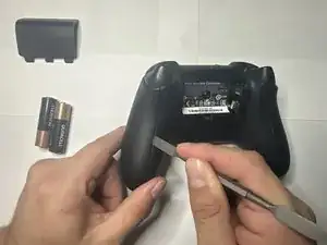
Start by flipping the controller over and opening the battery compartment located on the middle back of the controller.
-
Remove the batteries. Place both the cover and the batteries off to the side for now.
-
-
-
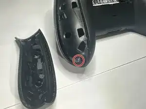
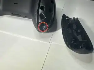
Next, take your opening tool and pry off the grip plates.
-
Using your opening tool, insert it into the grove found on the back of the grips.
-
Slide the tool throughout the groove, apply more pressure when you feel more resistance.
-
Repeat this until the grip cover comes off.
-
Do the same for the other grip.
-
-
-
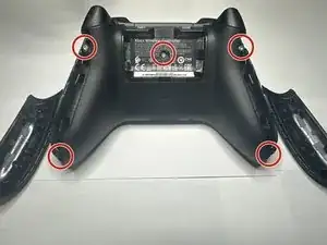
After removing the grip plates, remove the 5 screws holding the front plate.
-
The screws are shown in the picture with two in each grip and one in the battery bay.
-
-
-
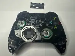
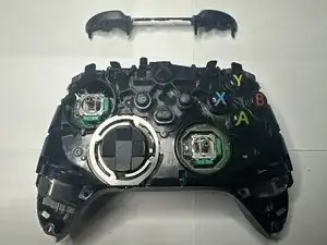
After removing the back screws, the face plate should be easy to remove. Remove it and place it to the side for later.
-
Next, locate the joysticks covers and remove them by simply pulling them up from the controller.
-
Place the joysticks off to the side.
-
-
-
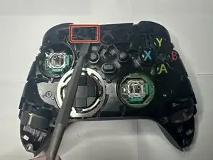
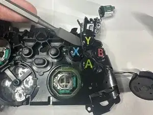
Place your spudger as shown and gently peel the sync button plate off using the same method as before.
-
Remove the plate and place it off to the side for later.
-
-
-
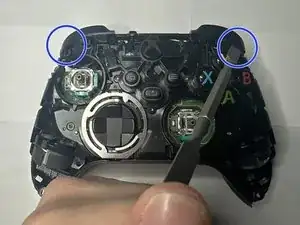
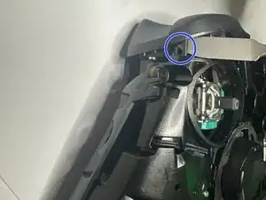
After that, locate the RB and LB bumper piece and using your metal spudger, place it between the frame and the hinge.
-
Gently pry the piece away and off, doing the same for the other end of the bumper piece.
-
Having done this successfully, the bumper piece should come off cleanly and with little effort.
-
Set the bumper piece off to the side.
-
-
-
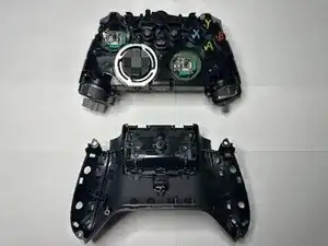
By now, the back plastic frame should simply fall off the main components.
-
Take the back piece off and leave it off to the side for now.
-
-
-
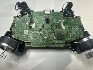
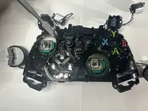
Take the main piece and flip it over to show the main components.
-
Next, we will be removing both triggers.
-
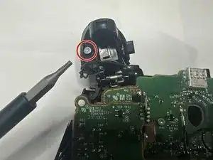
Move the triggers forward and expose the back parts of the trigger.
-
Using the T6 sized bit, remove the screw from the trigger and place it safely off to the side.
-
Do the same for the other trigger and set the pieces off to the side.
-
-
-
With the trigger frames out of the way, remove the trigger weights from the triggers and place them out of the way.
-
-
-
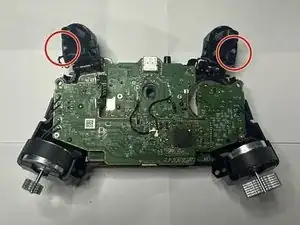
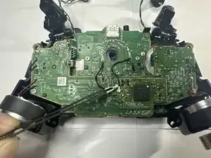
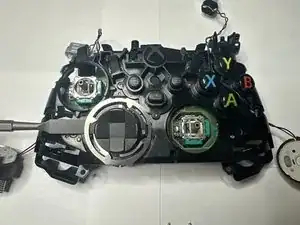
Next, we will disconnect the wires for the select and menu buttons.
-
Using either your fingers or a set of tweezers, gently pull the connection up and away to disconnect it.
-
Do this for both connections.
-
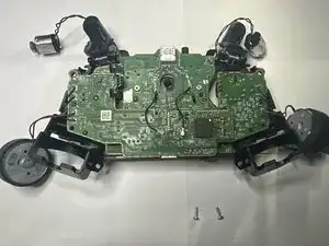
While here, remove the two screws above the connections. These connect the motherboard to the frame.
-
-
-
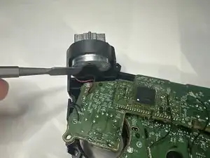
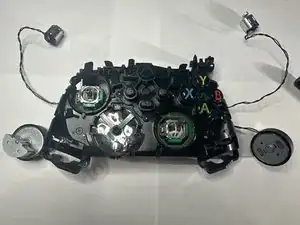
Next is the grip rumble weights.
-
Simply using your hands or forceps, remove the weights by sliding them towards you and lifting them out.
-
-
-
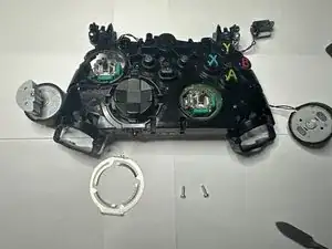
With both set of rumble weights out of the way, next is the board screws.
-
Using the T6 bit screwdriver, unscrew the screws located on next to where the grip rumble weights were.
-
Set these screws aside for now.
-
-
-
Flip the controller over.
-
Following the cord attached to the trigger it should be attached to the controller via small tracks.
-
Gently pull the wire out from the tracks and lay the wire and trigger parts out of the way.
-
-
-
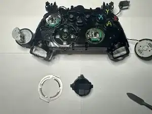
Find the D-pad plate surrounding the outer rim of the D-pad.
-
Using your spudger, slide it underneath the piece and pull it up from the controller.
-
Remove the plate and set it to the side.
-
Remove the D-pad from the controller and set aside for now.
-
-
-
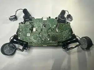
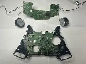
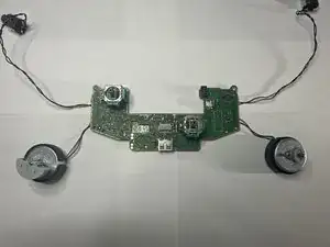
Isolate the motherboard. It will be attached to the joysticks.
-
Lay the board flat and observe for any debris or clear obstructions.
-
-
-
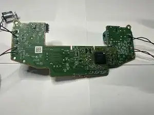
Flip the board over.
-
Locate the joystick solder nubs on the back of the bottom of the board.
-
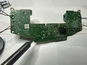
Using the soldering iron, heat it up to around 350-375 degrees Fahrenheit and lay the tip on the aforementioned nubs.
-
Hold it for around 5-7 seconds or until the solder nub liquefies. Repeat this for the rest of the nubs.
-
Having done this, the joystick should slide out the board. Install the replacement joystick by sliding in the joystick prongs into the slots that the old joystick sat in.
-
With the joystick in, solder the prongs until they are secured into place on the boards.
-


To reassemble your device, follow these instructions in reverse order.

4 comments
Granted I've only ever soldered and desoldered keyboards before, but I'm relatively sure that this is impossible without a hot air reflow station. Keeping all 10 solder joints hot enough to get the joystick out was impossible in my opinion, I couldn't do it. So much for those hall effect joysticks I bought...
David C -
Get a solder sucker or one of those copper thingys, they cost under 10 bucks and work just fine for stuff like this
ifixit themself made a video guide on this recently
Use solder wick (the copper thingy Verhulstak mentions) to get the solder sucked out of there. I think the video posted by ifixit has this process explained more thoroughly, I suggest you follow that.
Just watched the video that they put out and I'm considering trying again - I think my problem was that I was using low quality solder wick.
Not gonna lie, from using solder suckers fairly often I do not think that's the move here, solder wick is what you want to do. Cutting it like the video is also important, I didn't do that and I'm assuming that's why it didn't work for me the first time.
David C -