Introduction
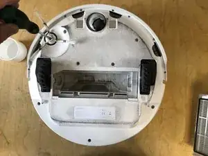
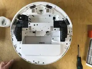
In this guide I will show you how to completely open the Roborock S5 (ROBOROCK S50200) to get to the components that are the most difficult to reach.
-
-
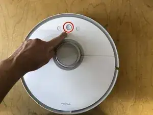
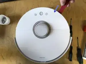
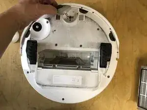
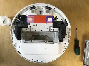
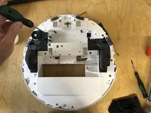
Insert the spudger from the side
-
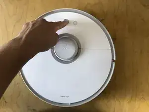
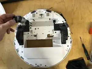
Release the clips by turning the spudger
-
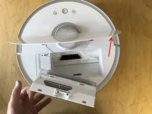
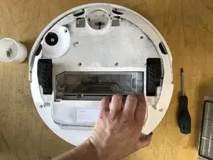
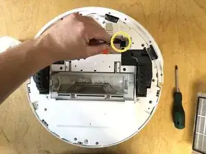
Lift the cover upwards
-
-
-
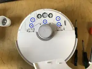
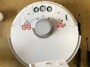
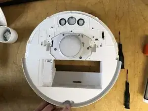
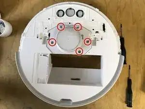
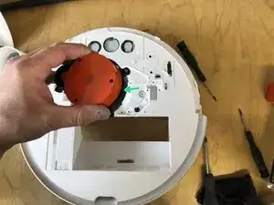
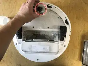
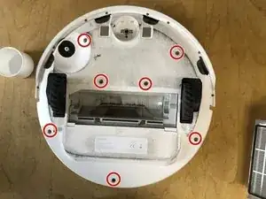
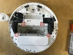
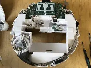
Remove the 4 screws of the laser unit
-
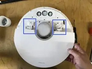
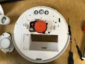
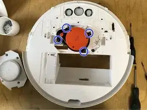
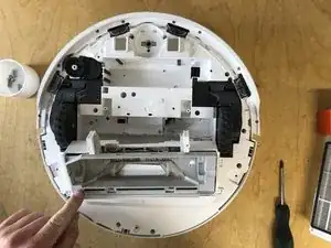
Remove the unit upwards (unit is still plugged into the circuit board)
-
-
-
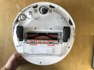
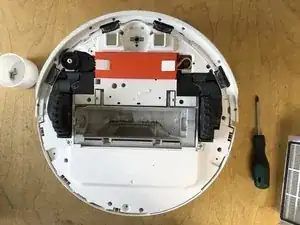
Remove the main brush holder by pressing both locks inward and lifting it up.
-
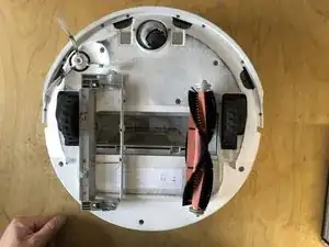
Remove the main brush.
-
-
-
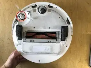
Remove the screw holding the side brush.
-
Remove the side brush along with the screw by lifting it upward.
-
-
-
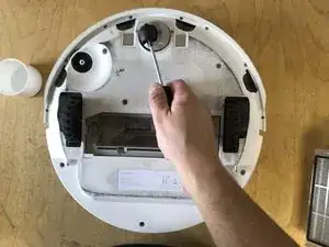
Lift the front wheel with the screwdriver.
-
Completely pull the front wheel upward to remove it.
-
-
-
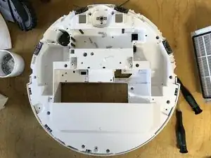
Remove the four screws from the main brush assembly
-
Lift out the main brush assembly upwards
-
-
-
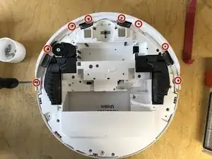
Remove the 8 screws from the underside of the bumper
-
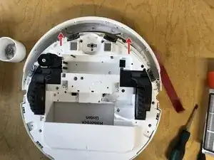
Remove the strip
-
Pull the bumper forwards, taking care not to bend the two metal plates
-
-
-
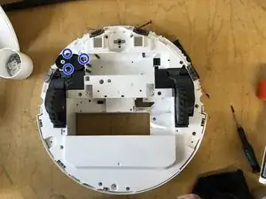
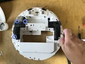
Remove the three screws from the motor
-
Pull the motor out upwards (plug connection with the circuit board)
-
-
-
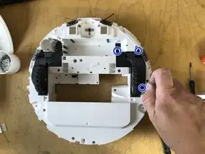
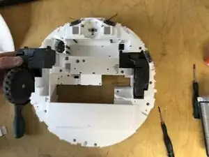
remove the three screws from the drive unit
-
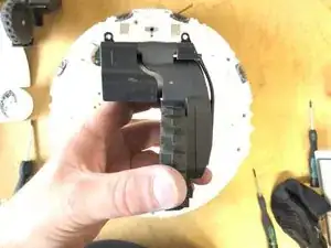
Remove wheel upwards (connected to a circuit board via plug connection)
-
-
-
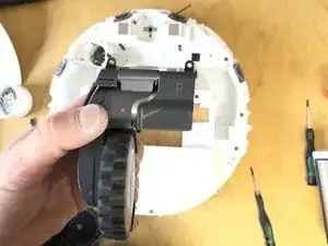
Remove the three screws from the drive unit
-
Remove the wheel upwards (connected to the circuit board via a plug connection)
-

Work through the steps in reverse order to reassemble your device