Introduction

prerequisite for logic board, heat sink, and CPU

  1. oLXPwREymEN3QugN
    oLXPwREymEN3QugN
    AVJCacHQsZVIsbBy
    vouYRyJZuOpihXt5
    • Remove the four 7.5 mm T8 screws from behind the GPU on the logic board.

    • These screws are set inside large, spring-loaded Phillips #2 screws. To prevent the larger screws from spinning when you loosen the T8 screws, hold them with a fingertip or Phillips #2 screwdriver.

  2. KiAS4hrEECx1ATOy
    • Remove the bracket from behind the GPU heat sink.

  3. QxaqVe1SYiE4MqHB
    • Remove four black stickers from the back of the CPU heat sink.

  4. c5wBcTUXOk1nRu3O
    • Remove four 12.3 mm T10 screws from the back of the CPU heat sink.

  5. 6AQH2jRQPJXaRw2G
    6AQH2jRQPJXaRw2G
    QM4XkyOn1Dp5b4Xb
    POFXPLvFeHu1LiPo
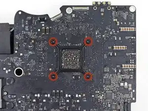
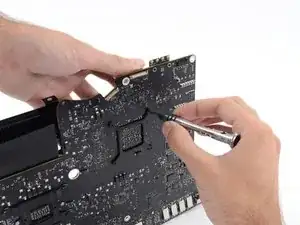
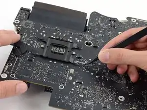
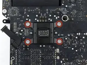
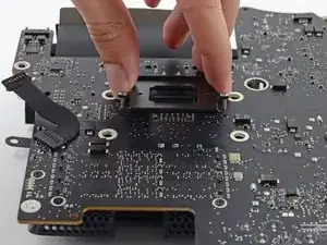
    • Remove the spring plate from behind the CPU heat sink.

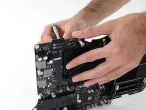
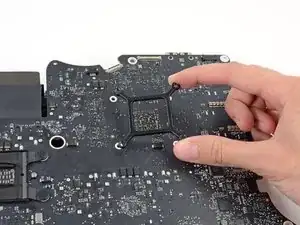
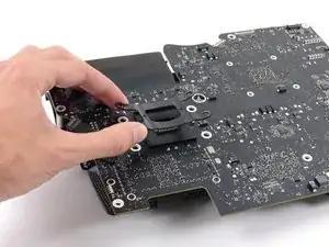
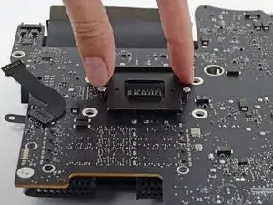
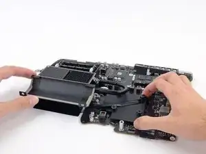
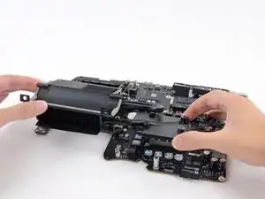
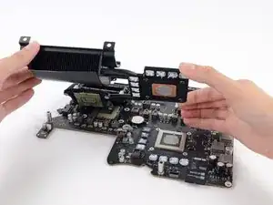
    • Lift and remove the backing plate from behind the CPU heat sink. The backing plate has two posts that fit into alignment holes in the logic board.

  6. qLVXLNydmKWQWanK
    qLVXLNydmKWQWanK
    Ne1ypyAMZ6OFnlVG
    24yDU6cMOi3WKGhN
    • Lift the heat sink up from the logic board.

    • The CPU will most likely stick to the heat sink, so be careful about where you put it down.

    C'est l'étape la plus importante : au moment de retirer le dissipateur, il faut faire très attention de ne surtout pas tordre ou endommager les pins du socket processeur ! Car la cage pour la RAM gêne le mouvement pour enlever le dissipateur et le CPU est probablement toujours collé au dissipateur avec la pâte thermique.

    Si les pins du socket CPU sont endommagés le Mac ne redémarrera pas et sera hors service.

    Je préconise d'ajouter une étape avant la 59 : démonter la cage pour la RAM, il y a 3 toutes petites vis et un peu d'adhésif. Cela permet d'être plus à l'aise avec le retrait du dissipateur.

    zhorglub -

Conclusion

To reassemble your device, follow these instructions in reverse order.

Andrew Optimus Goldheart

Member since: 17/10/09

508817 Reputation

0 comments