Introduction
Tools
Parts
-
-
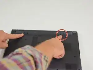
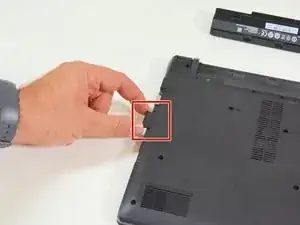
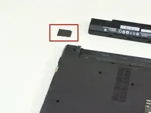
Start by unlocking the right locking latch.
-
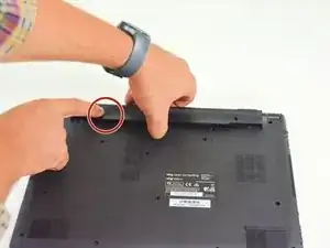
Then, by simultaneously unlocking the left latch, lift the battery out of its socket.
-
-
-
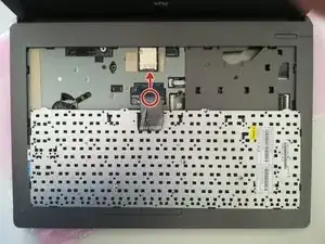
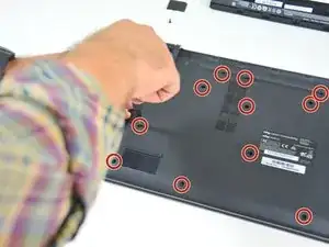
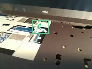
Unscrew the circled screws in green and red
-
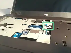
Put the computer in the position of the second image while pushing a paper clip into the hole of the screw circled in green until you hear a click
-
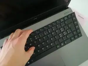
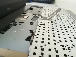
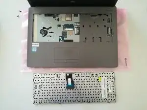
Lift the keyboard
-
-
-
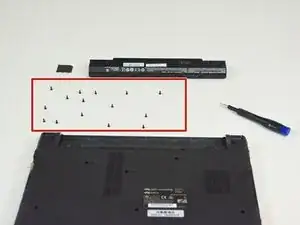
Locate the 15 screws that hold the bottom cover of the device in place.
-
Unscrew them and place them on your work surface.
-
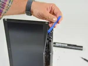
Then, un-clip the bottom cover, starting with the side shown in the third picture.
-
-
-
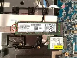
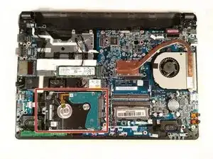
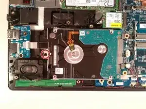
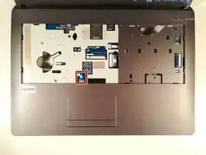
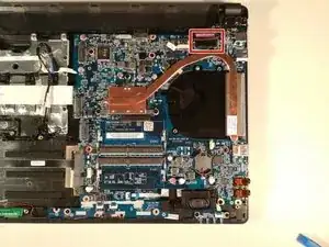
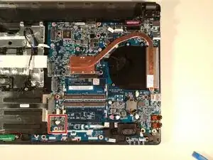
Remove the screw circled in red
-
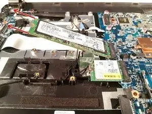
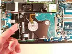
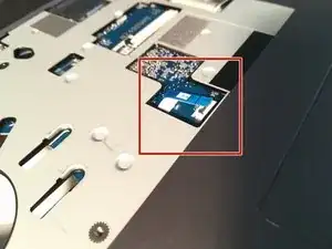
Lift up the hard drive
-
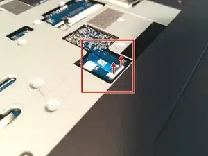
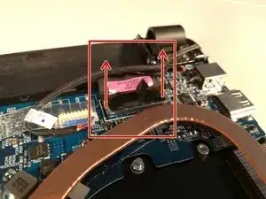
Remove the hard drive in the direction of the red arrows
-
-
-
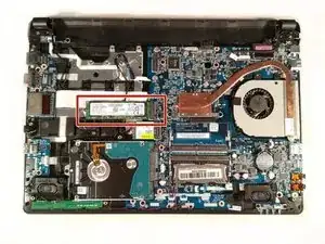
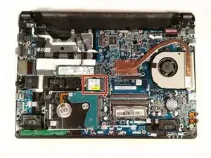
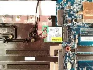
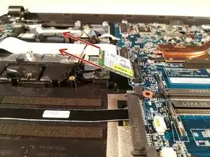
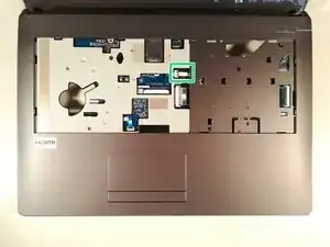
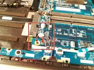
Remove the screw circled in red
-
Disconnect the two connectors marked in green
-
Remove the WLAN card
-
-
-
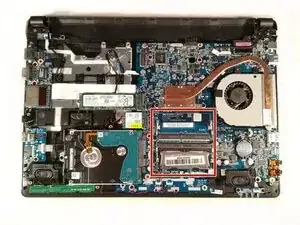
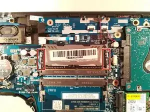
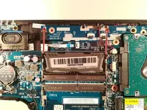
Press down on the two brackets boxed in red
-
Remove the RAM stick in the direction of the red arrows
-
-
-
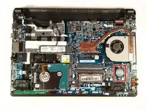
Press with a screwdriver in the red circled area to spread the base of the battery
-
Remove the battery by holding the screwdriver down
-
-
-
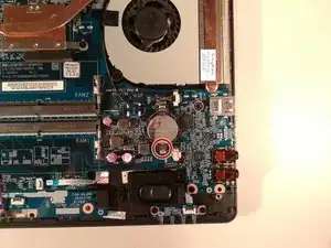
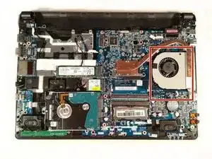
Remove the two screw circled in red
-
Disconnect the connector boxed in green in the direction of the green arrow
-
Remove the fan by lifting it up
-
-
-
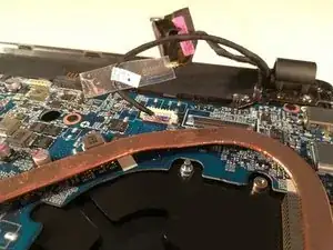
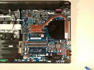
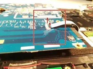
Lift the retaining flap off of the connector boxed in red.
-
Disconnect the connector boxed in red.
-
-
-
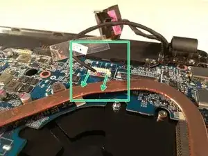
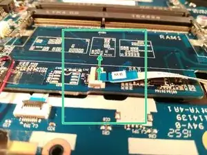
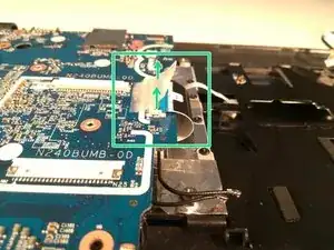
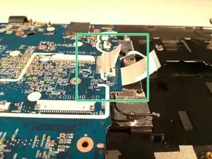
Lift the flap that holds the connector (framed in green)
-
Disconnect the connector (framed in green)
-
-
-
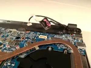
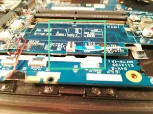
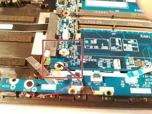
Lift the black retaining flap that holds the connector marked in green
-
Disconnect the connector marked in green
-
-
-
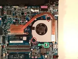
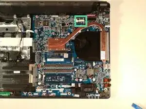
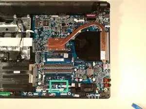
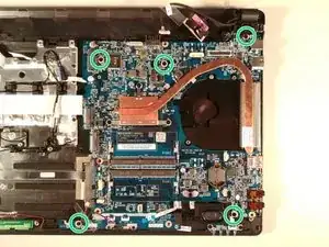
Unscrew the five screws circled in green
-
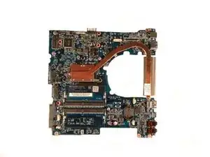
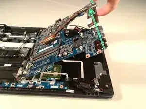
Lift the motherboard by taking it by the radiator as in the second picture
-
-
-
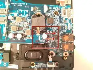
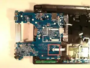
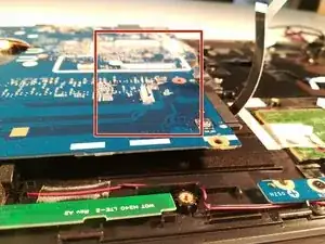
Lift the retaining flap that holds the connector marked in red
-
Disconnect the connector marked in red
-
-
-
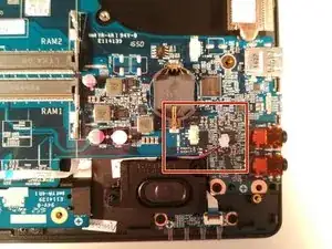
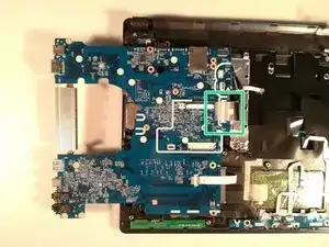
Lift the retaining flap that holds the connector framed in green
-
Disconnect the connector boxed in green
-
Remove the motherboard from the case.
-


To reassemble your device, follow these instructions in reverse order.