Introduction

Special Note: The computer's interior houses multiple sensitive parts. To eliminate any chance of damage due to electrostatic discharge (ESD), wear an ESD Grounding Strap or follow a proper grounding protocol to mitigate the risk.

To learn more about ESD and proper grounding methods, read this excellent iFixit article.

  1. o1nOhBpgFEffjFAO
    • Make sure to unplug the machine and press the power button to discharge any remaining electricity.

    • Place the computer on its side, with the HP logo and fan vent facing up, as shown.

  2. NnuQ2KvX1fNIwl6Z
    NnuQ2KvX1fNIwl6Z
    cZLUdEuR3Hh5mIAk
    KbIJpCOjIDGjYlBk
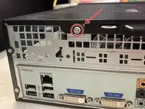
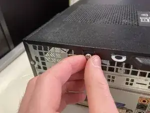
    • On the back of the machine, unscrew the rear screw securing the side plate. You should be able to do this with your hand.

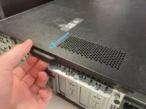
    • Using the handle, pull the plate towards the back of the machine to reveal the inside.

  3. wSb6HPLIi5BowqvD
    wSb6HPLIi5BowqvD
    BPepmTOpknCXMUHy
    P1bcaLmrOOVO6w6v
    • Pull up the three clips that hold the faceplate to the computer with your fingers.

    • The third clip on mine broke off, so be careful!

    • Pull out on the faceplate to remove it.

  4. Ow1RiKIYCfiAYl1I
    Ow1RiKIYCfiAYl1I
    IT4qRhqWXfDlaXOF
    • Push up on the optical disc drive to get access to the cables.

  5. QIr1iWZIyARWt6FH
    QIr1iWZIyARWt6FH
    tWMrpCXNpRgCRgpI
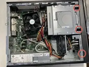
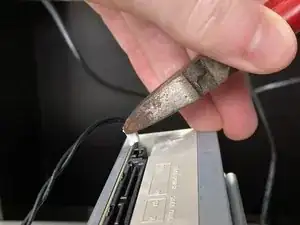
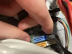
    • Unplug the center power cable between the two other cables on the ODD.

    • Unplug the right Serial ATA (SATA) data cable.

  6. x1sV3vuYPcNTZqNq
    x1sV3vuYPcNTZqNq
    N2YZVwhAHESek32e
    • Unplug the leftmost cable.

    • This cable was quite hard to pull out, so you may need to get some pliers to remove it.

    • Don't grab the cable while unplugging, as this can damage the connection.

    • This cable connects the ODD to the "Eject" button on the outside of the machine.

  7. X6ojtuCanEXNYjf4
    X6ojtuCanEXNYjf4
    pBEAiafoiUHiLMgV
    LrvSYxfVbGNlrD4X
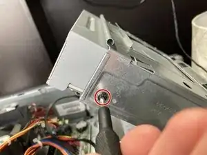
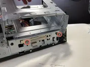
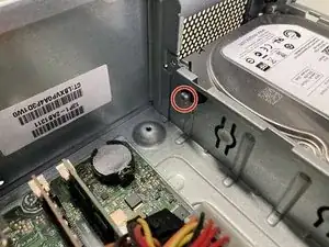
    • Remove the right-side screw holding the ODD in place.

    • Make a note of which screw hole the screw came out of. Mine came out of the "1" hole, but yours might be different.

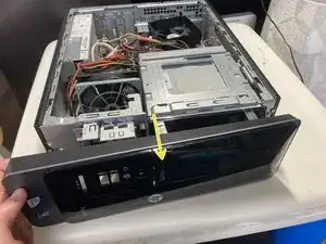
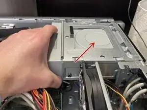
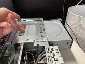
    • Slide the ODD out, using your fingers to push forward from the back.

  8. ZPkRwIjt6OtcxOJ6
    ZPkRwIjt6OtcxOJ6
    gOW4U51M4JmUjbLc
    • The disc drive is manufactured by Hewlett-Packard, model number DH-16ACSH. It can read and burn DVD/CD-RW discs, including dual-layer discs.

  9. X3UxDKDaOUaeKshO
    X3UxDKDaOUaeKshO
    G5wLZkwT3XlaTKaj
    • Unscrew the three screws holding the HDD in place.

    • There are three screws; two are outside near the top, and the other is inside the case near the top of the motherboard.

  10. bCJQq1LL3SCrMLAV
    bCJQq1LL3SCrMLAV
    1dqbtIH3eDZKmTYh
    CG2fXFGQtn6s2ISq
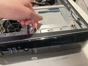
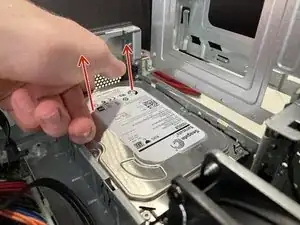
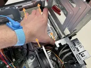
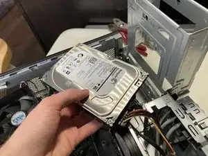
    • Pull up the back of the HDD to loosen it.

    • Use both hands to pull up the HDD to pull it out of the cavity.

    • Don't pull out the HDD completely, as it is still connected to cables.

  11. tAkrQvCQRXmH1BcY
    tAkrQvCQRXmH1BcY
    Nw1ORGjsNqrGwXDv
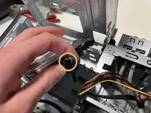
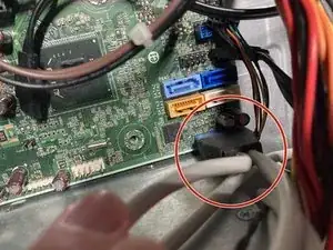
    • Unplug the power cable on the left-hand side.

    • Unplug the SATA data cable right next to the power cable.

  12. qCV6SCYkkpE42Ghg
    • The drive is a Seagate Barracuda 7200 RPM 1 TB SATA disk, model ST-1000DM003.

  13. xaA3ASJP4VAREKNA
    xaA3ASJP4VAREKNA
    yDMYQkRadVJvQu3N
    JMZUsMbmBLlLUJn3
    • Make sure you are grounded using an ESD Grounding Strap or other grounding method before touching the RAM. Failure to do so may result in damage to the RAM.

    • To learn more about ESD and proper grounding methods, read this excellent iFixit article.

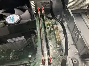
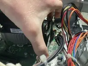
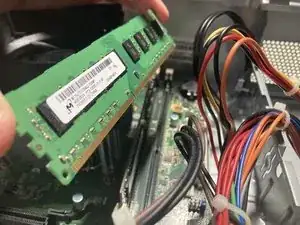
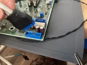
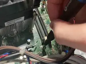
    • Push the four clips outward, and pull the RAM sticks straight out.

  14. fNRLBA1ljSZePCWf
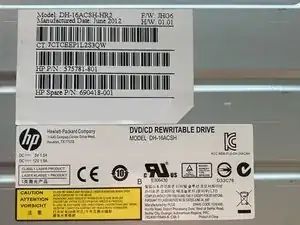
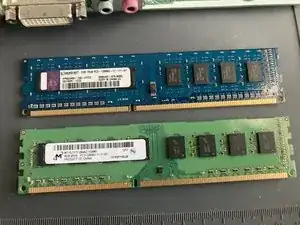
    • The top stick is a Kingston 2 GB module labeled as HP655409-150-HYCG. It has 8 SK Hynix 512 MB chips.

    • The bottom stick is a Micron 4 GB module labeled as MT16JTF51264AZ-1G6M1. It has 16 Micron 512 MB chips.

    • This PC came with 6 GB of DDR3 1066 MHz RAM.

  15. kf25dVXsKsofbNxO
    kf25dVXsKsofbNxO
    eTwB2YgekQU24aLs
    ELiOYXWUdLlCvo6a
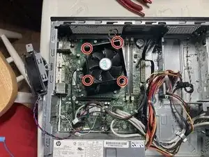
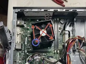
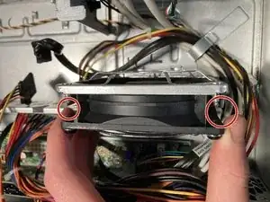
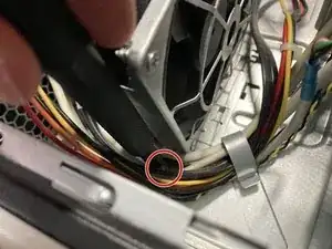
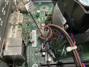
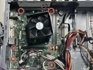
    • Unscrew the four silver screws that hold the heatsink assembly down in a star pattern, as shown, starting with the one marked by the blue circle.

    • Do not remove the black screws. These are for holding the fan to the heat sink. The silver screws hold the heat sink against the CPU. Also, the silver screws don't come out, they only unscrew.

    • Failure to unscrew the screws a little at a time using a star pattern may result in motherboard damage.

  16. rmPbGLOYbfwaxl2v
    rmPbGLOYbfwaxl2v
    xD1YDryP6CEx1rC1
    4GIWYcQ6SolsotMu
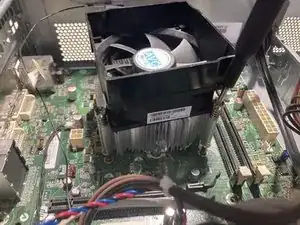
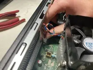
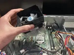
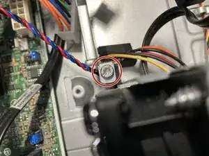
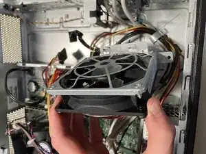
    • Unplug the CPU fan power cable located above the heat sink assembly and near the top of the case.

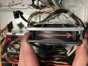
    • Remove the heat sink assembly.

  17. 4XmhCKYCHAxtEuBl
    4XmhCKYCHAxtEuBl
    NLpWPdPiivv5SWLV
    u6qEFXbDtpueV3tb
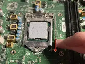
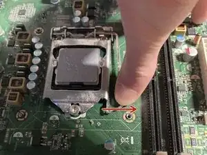
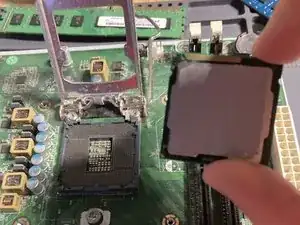
    • Push the lever holding the CPU down and to the left.

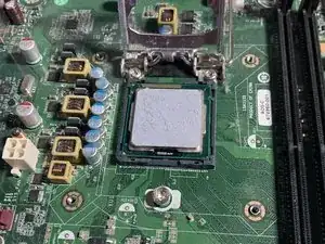
    • Open the plate holding the CPU down and remove the CPU.

  18. nopONaI2eZHDNBgX
    • The CPU is an Intel Pentium G640 with two cores and a clock speed of 2.8 GHz.

  19. m32glHFmJ5qGNXte
    m32glHFmJ5qGNXte
    LPi4aTA5MxdMjcaa
    Z1vn5iRyOkKBRXV1
    • Unplug the circulation fan power cable.

    • You may need to cut the zip tie holding the CPU power cable and the circulation fan's cable together if you wish to remove the fan entirely.

  20. D2Zdn5VRam6mQLfN
    D2Zdn5VRam6mQLfN
    ZPPbBNuDaqYsJOvq
    cQtsJVED25HrAUMB
    • Unscrew the two screws at the top and bottom of the fan, holding it in place.

  21. lmYWygfJDuYjTE6L
    lmYWygfJDuYjTE6L
    dqHOorDDBlMrRcQ5
    • These photos are rotated so they can fit without cropping. The arrow is pointing down towards the case.

    • Slide the fan down towards the bottom of the case, then lift it out.

  22. xZQnPVWWQk4TYV2I
    xZQnPVWWQk4TYV2I
    TAhleDbmZgVOoJ2S
    • Unplug the motherboard's power cable on the right-hand side.

  23. DvNGwtRZpw4ltPNj
    DvNGwtRZpw4ltPNj
    CcYOsGRuOeBuTKid
    • Unplug the CPU's power cable on the left-hand side.

  24. KNnTJGk1UINPPuZa
    KNnTJGk1UINPPuZa
    qmowxilG4xhmksj3
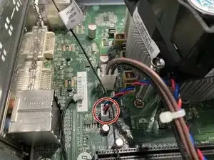
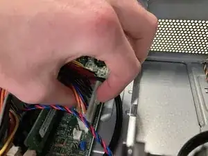
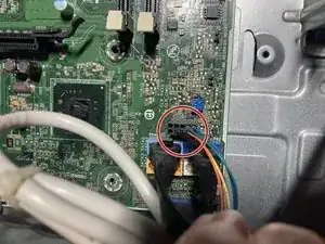
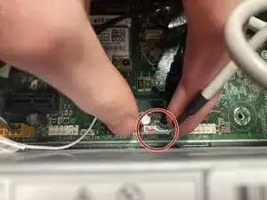
    • Unplug the cable right above the SATA ports on the bottom right-hand side of the motherboard.

    • This cable connects the power button to the motherboard.

  25. Lcf5dGGfXGnsco2B
    Lcf5dGGfXGnsco2B
    t6LpJocFMMHvFN3d
    • Remove the two SATA cables.

    • Make sure to note which cable comes out of each port. The HDD should be connected to the dark blue "SATA0" port, and the ODD should be connected to the light blue "SATA2" port.

    • The dark blue is SATA0, the white is SATA1, the light blue is SATA2, and the yellow is SATA3.

  26. ljdtFcNUn2fvH5fv
    ljdtFcNUn2fvH5fv
    dEEMquvBMPNOJsg3
    • Unplug the big cable with two cables coming out.

    • This cable handles the USB 3 connection coming from the two ports on the front.

  27. BKDmPRA3UAJtIrrJ
    BKDmPRA3UAJtIrrJ
    F3AKxTMoEDrA4b2m
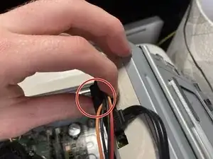
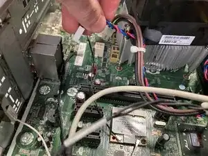
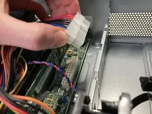
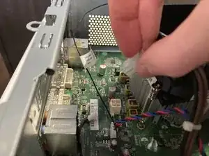
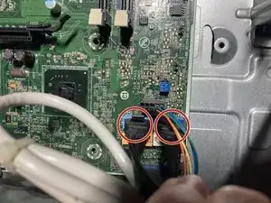
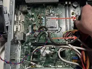
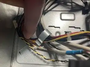
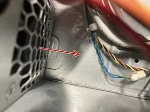
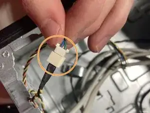
    • Unplug the white slim cable near the top of the power supply.

    • Unplug the fatter orange cable to the left of the other cable.

    • You are unplugging different ends of the same cable that handles audio. I assume that this cable connects to an internal USB 3 connection and then sends the audio to a dedicated audio port. (My opinion, so don't quote me on that.)

  28. AXJM5qKxTIysmQyA
    AXJM5qKxTIysmQyA
    4CtmybQTFkG3DK3Z
    • Pardon the components you've already removed; I took this photo before I did many of the steps that came before.

    • Remove the six screws that hold the motherboard down.

  29. 1OyCsduVHrVfjntg
    • Pull the motherboard to the left and out to remove it from the case.

  30. tNCTvUUeDQqNM4yn
    tNCTvUUeDQqNM4yn
    APPYKTJikLpeOFvg
    TLFrJooIlDvuWY1e
    • The motherboard is an HP ATX board, model PCLDV0GD62R9LT. It has two DIMM slots, one 16x PCI Express port, four PCI Express ports, four integrated USB 2 ports, USB 3 capability, gigabit ethernet, dual DVI video out, dedicated audio out ports, and four SATA connections.

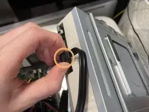
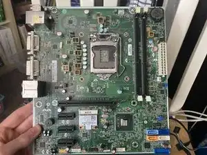
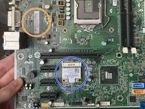
    • This motherboard also has a Mini PCI Express slot, which originally wasn't filled. I added a Wifi module that I swapped from another computer, and it works.

    • You could probably add a discrete GPU in here using the 16x PCI Express slot, but you should consider the PSU's limitations and other factors before choosing one.

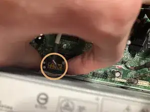
    • You can find the motherboard info in the orange circle.

  31. RrTXCnK63yLdT1Mv
    RrTXCnK63yLdT1Mv
    FYfDTYbjAARYrFeP
    ndSwhVLqwiLdIqd5
    • Pull out all wires under the clip on the right-hand side in front of the PSU.

  32. lEIHEHQk3fMWaZqQ
    lEIHEHQk3fMWaZqQ
    Te6ZKFTmTTVYbr6g
    • Remove the four screws on the back of the machine securing the PSU to the case.

  33. H3tZIoBsrPtfqlO2
    H3tZIoBsrPtfqlO2
    4XCBUDIQZgElL5Z1
    YkaCmBy2Qi2N6bGN
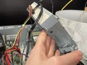
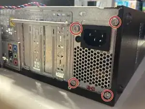
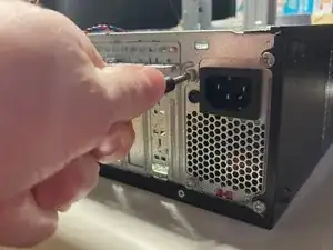
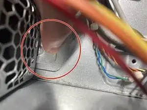
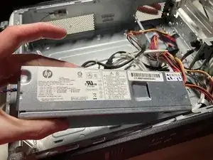
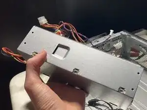
    • There is a clip at the front of the PSU that holds it in place. Press it down, and slide the PSU to the right to remove it.

  34. YbgFREPkeGQJlAag
    YbgFREPkeGQJlAag
    1SFhvatxCGFfVjjh
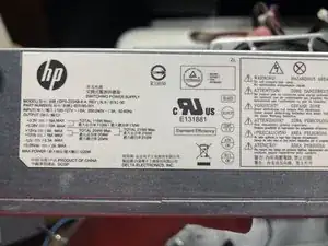
    • The PSU is branded by HP but made by Delta Electronics. The PSU has a maximum rating of 220W, which is fairly low by today's standards. The PSU's model number is DPS-220AB-6.

  35. bKCkfsiGIgBKAjVk
    bKCkfsiGIgBKAjVk
    aW1q1Rdo1ilGdhMY
    D5EtEnRUUEWS6FmP
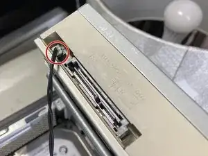
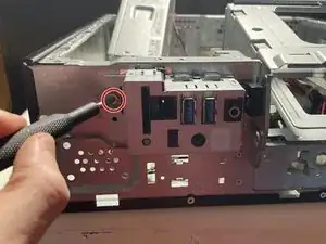
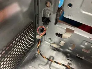
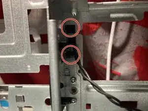
    • Unscrew the screw on the front of the machine holding the hub in place. The screw will not come out, just unscrew.

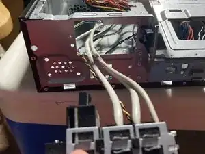
    • Unplug the bottom cable on the back of the hub.

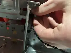
    • Pull the hub out. See the next step for unplugging the yellow and back cable from the power button.

  36. hWtXeirVrdlxaKsJ
    hWtXeirVrdlxaKsJ
    FnbxFO3BwALXPevV
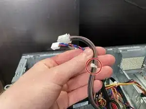
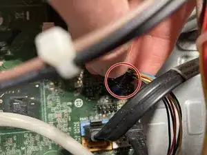
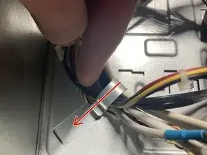
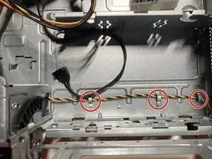
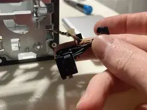
    • Remove the orange, yellow, and black braided cable located underneath the ODD bay, where the HDD goes.

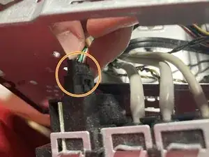
    • Follow the cable until you get to the part where it connects to another cable. Unplug them. (You may now fully remove the I/O Hub from the previous step.)

  37. GWaHiKhKyThmxRG4
    GWaHiKhKyThmxRG4
    1VW4QHpmyVh55q1V
    Vlu5s2Udby15UYbN
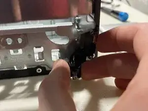
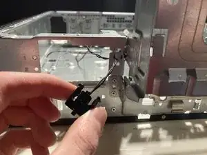
    • From inside the machine, undo the clip and remove the power button from the front, threading the cable.

  38. dJuZOqMlxMZ4KrLF
    dJuZOqMlxMZ4KrLF
    boApMxOjTyaKFbGf
    ojQbegEJWWQnPlw2
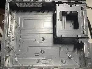
    • There are two clips inside the machine for the eject button near the middle. Pinch together the two clips from inside the case and pull the button out through the front.

  39. jIaw1Wg4FgguLYKp
    • The empty computer case! I hope you enjoyed this teardown.

Jerome Voskov

Member since: 05/09/24

703 Reputation

0 comments