Introduction
-
-
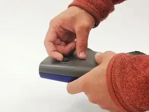
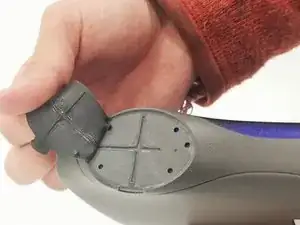
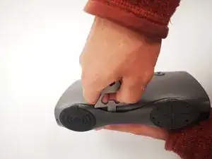
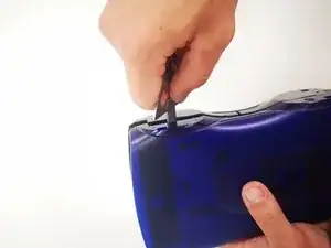
Rubber pads and feet are removed using your hands and needle nosed plyers.
-
The bigger pads are held on with glue and the smaller ones are fastened using a snap in system.
-
-
-
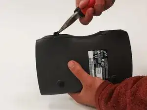
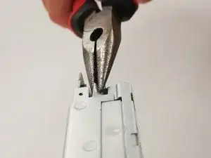
Use Flat head screw driver to disloge snap locks located along the seam of the enclosure.
-
The snap locks WILL break during disassembly.
-
Remove the blue upper section with the joined grey side panels to reveal the internals.
-
From here there are five parts: the internal casing, the top and bottom, and each side.
-
-
-
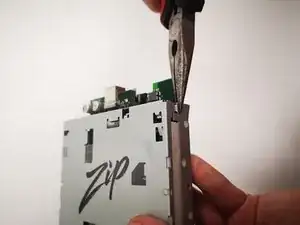
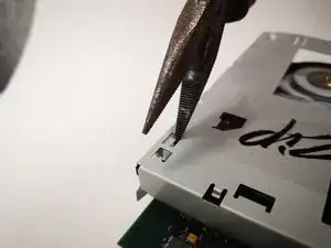
Twist the two tabs near the connector ports to disengage them.
-
Carefully use needlenose pliers to do this.
-
-
-
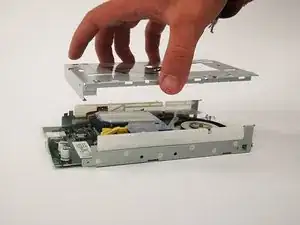
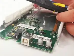
Lift four tabs located on the top panel and then remove the panel from the res of the housing. This should reveal the PCB and other mechanical components.
-
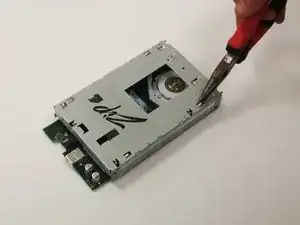
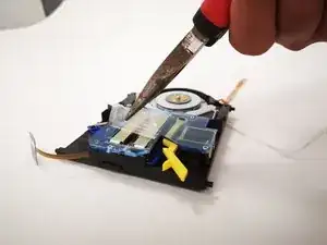
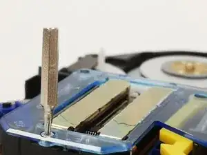
Use a thin flathead screwdriver or the needle-nose pliers to fit into the small hole.
-
-
-
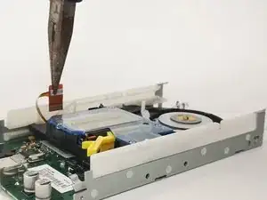
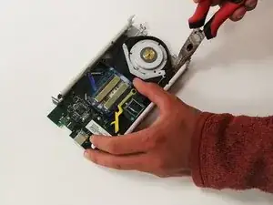
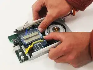
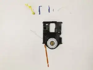
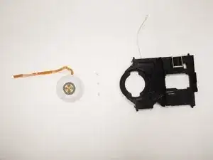
Remove the small spring from the front of the disk reader then move the reader back until you hear a click.
-
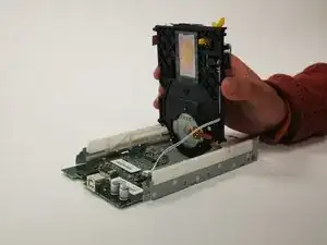
After this, raise the black component straight up and out of the metal chassis.
-
-
-
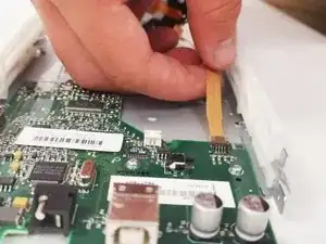
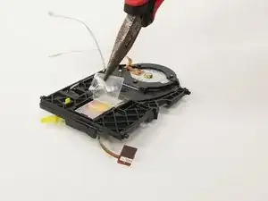
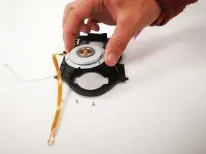
Remove the plastic film on the blue cover.
-
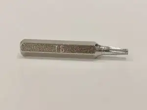
Remove the 4 screws holding this down with the T6 driver from before.
-
-
-
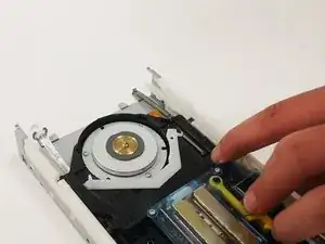
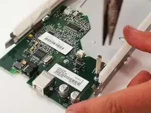
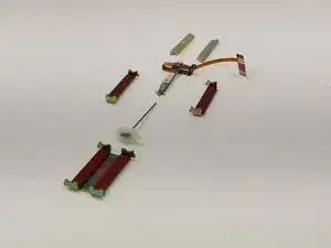
Remove the plastic film from the bottom of the disk reader and then remove the metal magnetic sub-assembly.
-
This is able to be dismantled by hand.
-
-
-
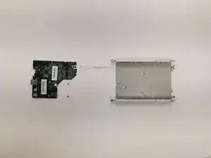
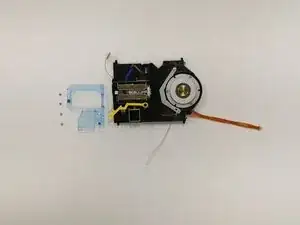
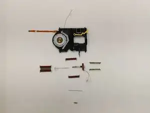
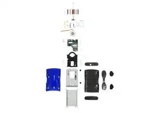
Once all the components have been disconnected, you should end up with all these pieces.
-
Note: The Voice Coil Actuator (VCA) has been disassembled in this image. Once removing the cover, the VCA will fall apart if not held together.
-


One comment
With a little bit of patience, it is possible to separate the top and bottom without breaking the tabs. This easier to do if you push in the little holes on the bottom near the feet to aid in removing the end cap (where the feet are).