Introduction
Replacing the vanes of a 5” Standard Series: Non-Vacuum-Airvantage Tool is a fast and easy process. Pneumatic orbital sanders such as this are quite expensive, and the problem is a small one that anyone can fix, making the purchase of another sander unnecessary. The tools required to replace the vanes of the sander may not be readily available in ones' work environment, therefore they can be purchased at a Home Depot or an Ace Hardware warehouse.
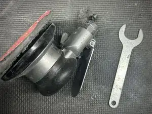
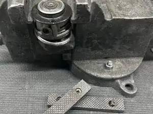
Tools
-
-
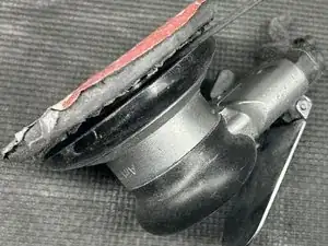
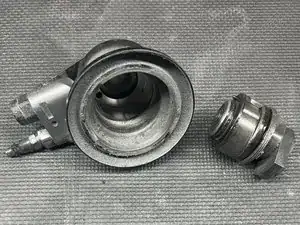
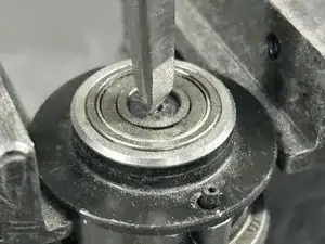
Clamp the sander's housing at a slight angle in a table vise.
-
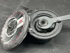
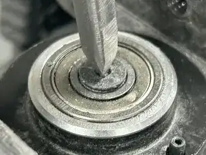
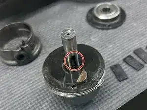
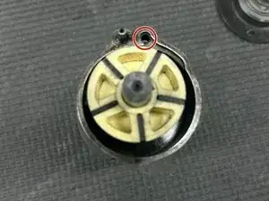
Place a prying tool against the orbit shaft balancer's ridge.
-
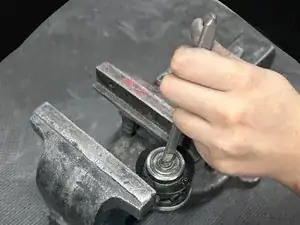
Gently tap the prying tool with a hammer counterclockwise to unscrew the main body from the shell.
-
-
-
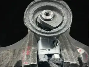
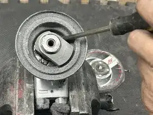
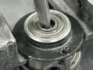
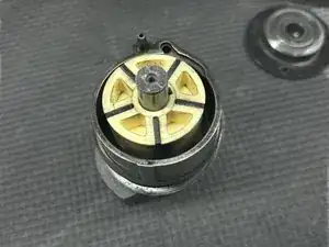
Remove the jaw faces of your table vise and place the main body into the clamp on the edges by the front endplate.
-
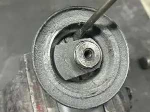
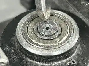
Place a pointed chisel directly in the middle of the orbit shaft balancer.
-
Use gentle to moderate strength to hammer out the shaft balancer.
-
-
-
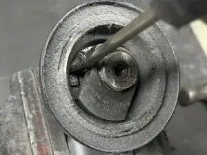
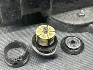
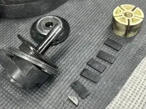
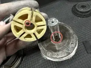
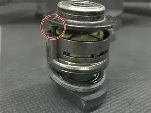
Remove this piece from the rotor and replace the old vanes with your new ones.
-
After removing the rotor, the woodruff key will slide out.
-
Place this back inside its slot before placing the rotor back onto the orbit shaft balancer.
-
-
-
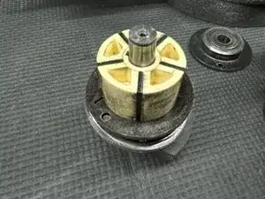
Line the rotor up with the indent and gently slide the rotor back into place with the vanes in the rotor.
-
-
-
Place the cylinder assembly part on the front endplate, making sure to line up the holes in both pieces to allow adequate air flow.
-
-
-
Place the rear endplate on top of the cylinder assembly, again lining up the hole in the rear endplate to the tube in the cylinder assembly.
-
Gently hammer the pieces together.
-
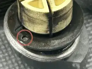
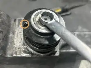
Take the head of a 3/8 wrench and use the hammer to gently push the bearing into the shaft to secure the main body.
-


To reassemble your device, follow steps 1 and 2 in reverse order.