Introduction
Use this guide to replace the thermal paste in your Mac mini (2024).
This guide was written with a baseline M4 Mac mini. Although the internals for the M4 Pro version are slightly different, the disassembly procedure is the same.
The thermal paste in your Mac mini will deteriorate over time and might affect your processor's performance. This guide shows how to replace the thermal paste to keep your Mac mini running smoothly.
You need to replace the thermal paste every time you remove the heat sink. This guide doubles as a heat sink replacement.
Tools
Parts
-
-
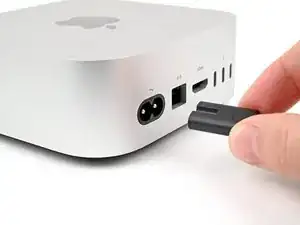
Fully shut down your Mac mini and unplug all cables from it.
-
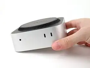
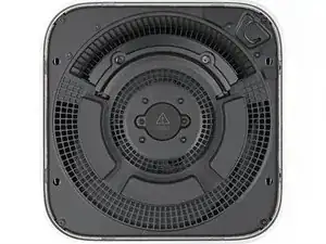
Flip over your Mac mini and place it on a clean, flat surface to avoid scratching the chassis.
-
-
-
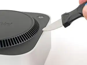
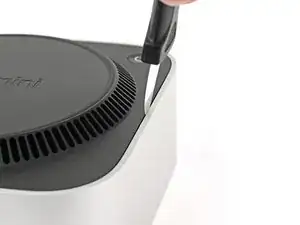
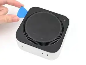
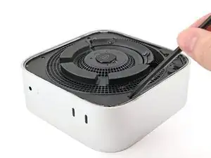
Insert a Jimmy into the gap between the bottom cover and the chassis.
-
Pry up the bottom cover to create a gap.
-
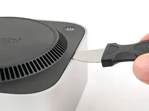
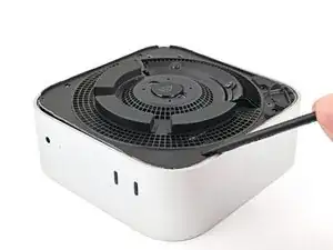
Keep the Jimmy inserted under the bottom cover.
-
-
-
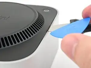
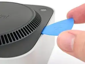
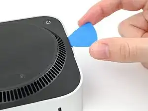
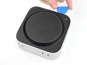
Slide the opening pick along the bottom cover until you feel it snag on a clip.
-
Twist the pick to lift the clip out of its slot.
-
-
-
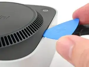
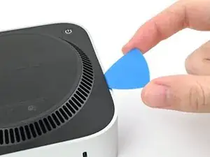
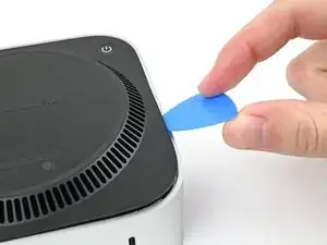
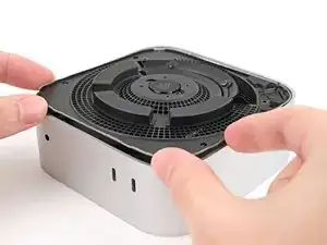
Continue sliding and prying with the pick along the perimeter of the bottom cover to release the remaining clips.
-
-
-
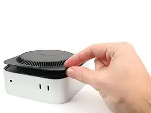
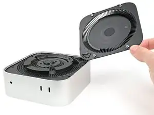
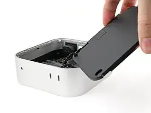
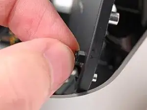
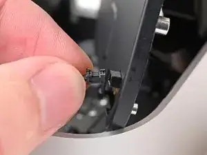
Lift the edge of the bottom cover opposite the power button and flip it over to expose the power button cable.
-
-
-
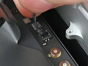
Grip the power button cable close to the head and pull it away from its socket to disconnect it.
-
-
-
Use a T5 Torx screwdriver to remove the twelve screws securing the inner plate:
-
Eight 3.4 mm‑long screws
-
Four 2.4 mm‑long screws
-
-
-
Insert the point of a spudger into one of the clips' slots on the inner plate.
-
Pry up the inner plate enough so you can grip the edge along the same side as the headphone jack.
-
-
-
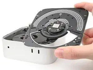
Pull the inner plate away from the chassis to slide it out from under the lip on the heat sink.
-
-
-
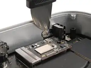
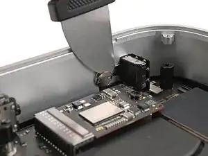
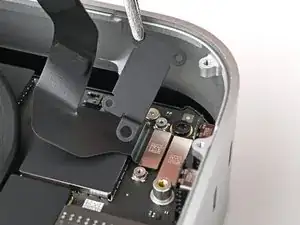
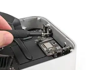
Use one hand to secure the wireless module during this step.
-
Use a Torx Plus 5IP screwdriver to remove the four 2.5 mm‑long screws securing the wireless module cover.
-
-
-
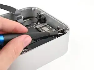
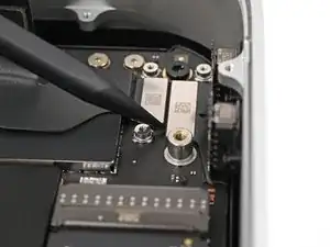
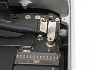
Use one hand to secure the wireless module during this step.
-
Insert the point of a spudger under one of the short edges of the wireless module press connector.
-
Pry up to disconnect the wireless module.
-
-
-
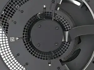
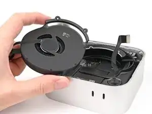
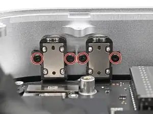
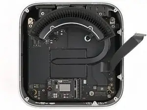
If you're following this guide to clean your fan, this is a good time to do so.
-
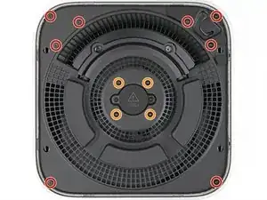
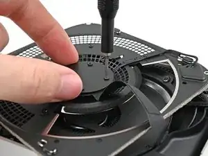
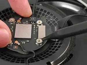
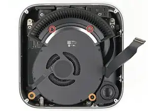
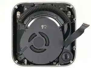
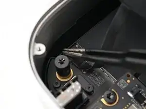
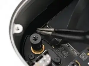
Remove the four screws securing the fan:
-
Two 2.4 mm‑long Torx Plus 3IP screws
-
Two 7.9 mm‑long Torx Plus 5IP screws
-
-
-
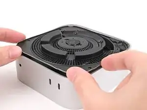
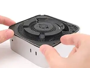
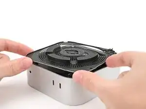
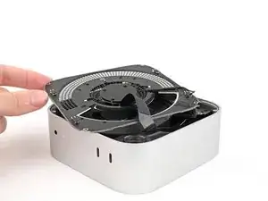
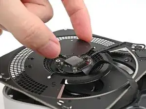
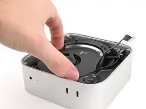
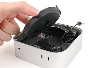
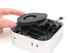
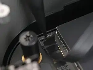
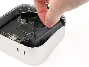
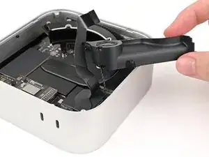
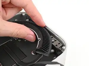
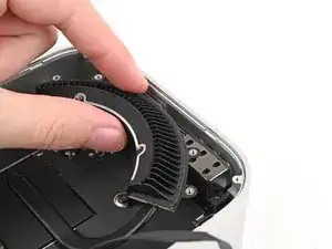
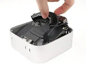
Lift the fan out of its recess in the chassis and flip it over to expose its wire and connector.
-
Let the fan rest on the chassis and heat sink.
-
-
-
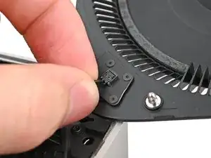
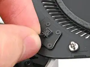
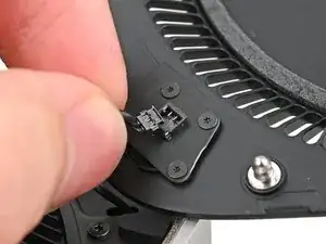
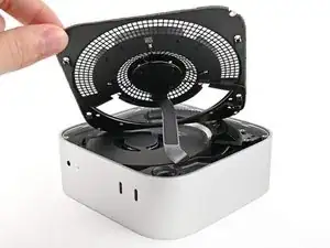
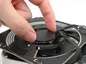
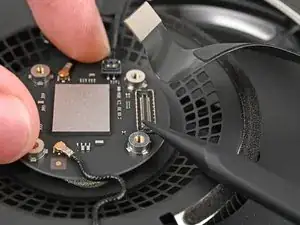
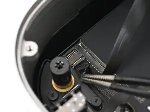
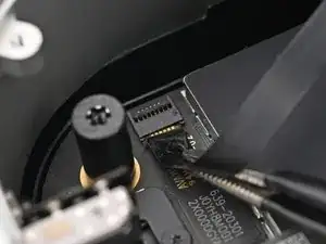
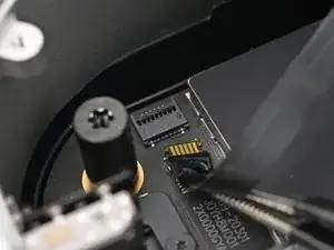
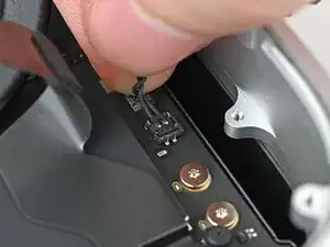
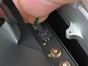
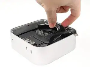
Use the point of a spudger, or your fingernail, to flip up the locking tab on the fan ZIF connector.
-
-
-
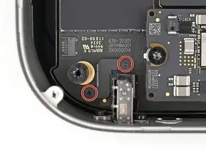
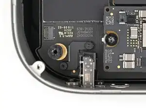
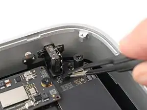
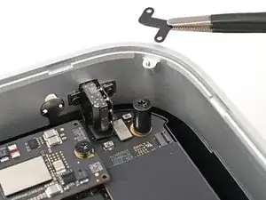
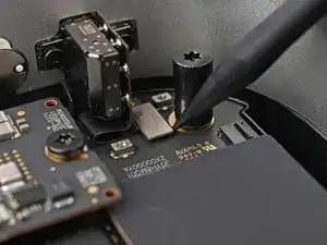
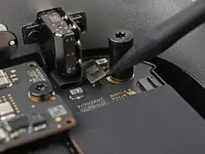
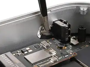
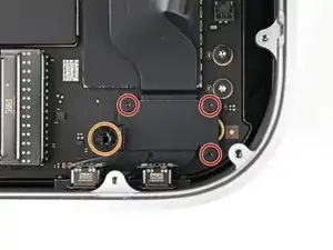
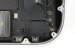
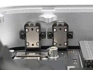
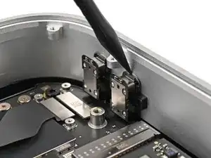
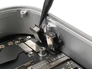
Use a Torx Plus 3IP screwdriver to remove the two 2.2 mm‑long screws securing the headphone jack cover.
-
-
-
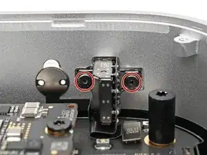
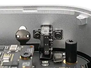
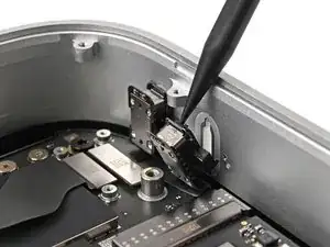
Use a Torx Plus 3IP screwdriver to remove the two 4.0 mm‑long screws securing the headphone jack.
-
-
-
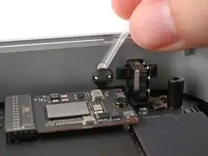
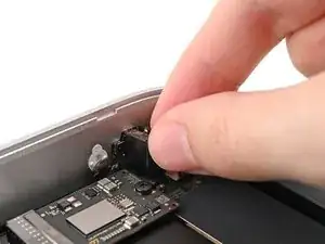
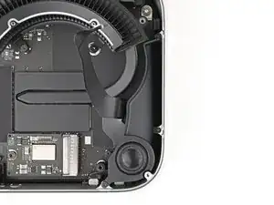
Apply a few drops of isopropyl alcohol (>90%) to the top of the power indicator's silver plate.
-
Wait one minute for the alcohol to flow behind the power indicator and for the adhesive to loosen.
-
-
-
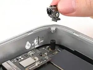
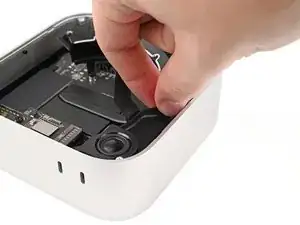
Slide a Jimmy between the top of the power indicator and the chassis to separate the adhesive.
-
-
-
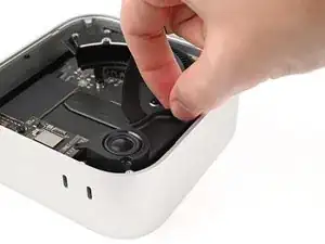
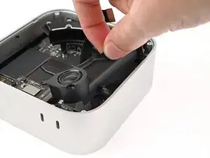
Lightly grip the power indicator with tweezers and pull it away from the chassis to separate the adhesive securing its cable.
-
-
-
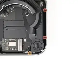
Use a Torx Plus 5IP screwdriver to remove the three screws securing the speaker:
-
Two 4.1 mm‑long screws
-
One 3.7 mm‑long screw
-
-
-
Pull the speaker over the edge of the chassis to expose its cable and its connector.
-
Rest the speaker on the edge of the chassis.
-
-
-
Remove the four screws securing the USB-C port cover:
-
Three 2.2 mm‑long Torx Plus 3IP screws
-
One 9.2 mm‑long Torx Plus 8IP screw
-
-
-
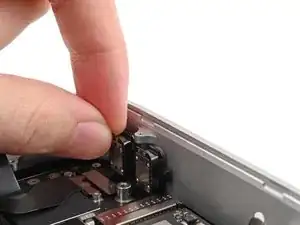
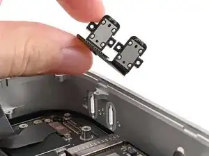
Use a Torx Plus 3IP screwdriver to remove the four 4.7 mm‑long screws securing the two front USB-C ports.
-
-
-
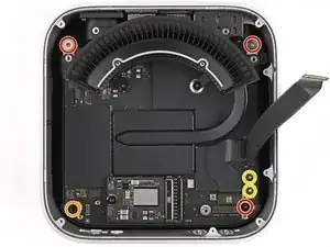
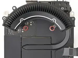
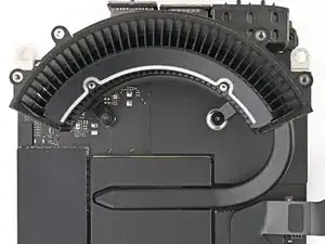
Remove the six screws securing the logic board:
-
Three 6.8 mm‑long T8 Torx screws
-
One 16.2 mm‑long T8 Torx screw
-
Two 4.2 mm‑long T5 Torx screws
-
-
-
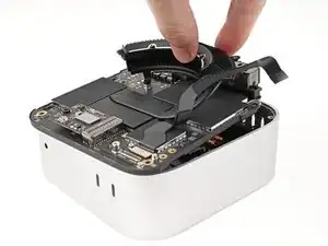
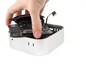
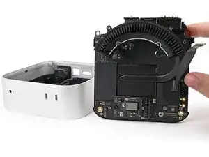
Lift the rear port side of the logic board out of the chassis before sliding the opposite end out.
-
-
-
Use your fingers to grip the power supply cable connector and pull it straight out of its socket to disconnect it.
-
-
-
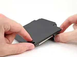
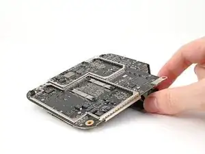
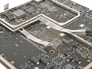
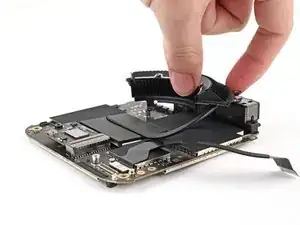
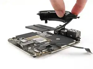
Flip over the logic board.
-
While securing the logic board with one hand, use the other to peel off the rubber cover.
-
-
-
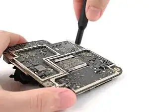
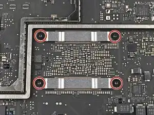
Use one hand to secure the logic board during this step to prevent damaging it.
-
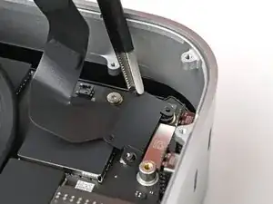
Use a Torx Plus 5IP screwdriver to remove the four 4.4 mm‑long screws securing the heat sink bracket.
-
-
-
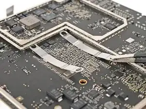
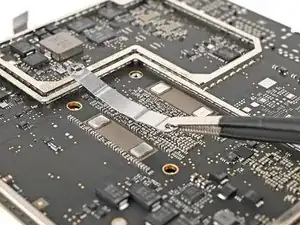
Flip over the logic board.
-
Use a Torx Plus 5IP screwdriver to remove the two 4.0 mm‑long screws securing the heat sink.
-
-
-
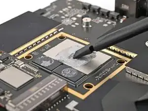
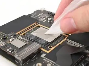
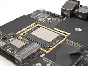
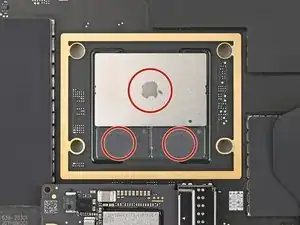
Use the flat end of a spudger to scrape off the old thermal paste from the processor.
-
Apply a few drops of isopropyl alcohol (>90%) to the processor and use a coffee filter or a lint-free cloth to wipe away any residue.
-
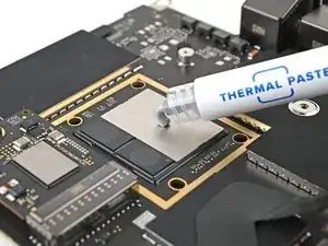
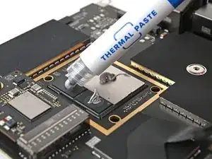
Repeat this step for the thermal paste on the heat sink.
-


To reassemble your device, follow these instructions in reverse order, starting with this step.
Repair didn’t go as planned? Try some basic troubleshooting, or ask our Mac mini (2024) Answers Community for help.

Den Mac vorm ausschalten noch vom Account trennen. Sonst kann es zu Schwierigkeiten bei der Neuanmeldung kommen.
MacGyverModeOn -