Introduction
Use this guide to replace the thermal putty and thermal paste in your Xbox Series X (2TB Galaxy Black).
The thermal paste in your Xbox will dry out over time and will affect the processor's cooling and overall performance. The thermal putty is more durable, but it can still dry out or tear during disassembly. Follow this guide to replace the thermal paste, putty, or both.
You need to replace the thermal paste every time you remove the motherboard. This guide doubles as a motherboard replacement.
-
-
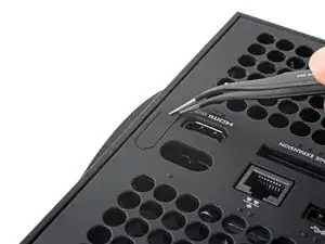
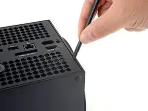
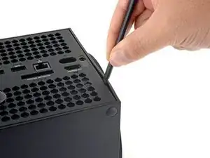
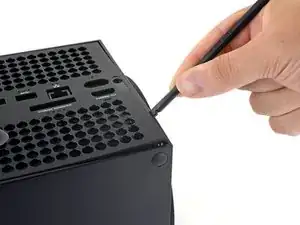
Use a pair of tweezers to remove the sticker hiding the first screw on the back panel, near the base.
-
-
-
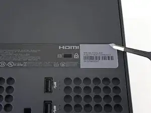
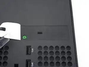
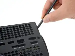
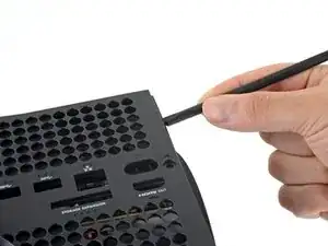
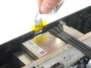
Use a pair of blunt tweezers to peel back the large sticker on the back panel to reveal the second screw.
-
-
-
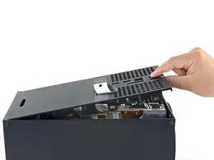
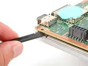
Insert the flat end of a spudger into the gap between the back panel and the shell, near the left side of the base.
-
Pry up the back panel to release it from the locking clips.
-
-
-
Insert the flat end of a spudger into the gap between the back panel and the shell, near the right side of the base.
-
Pry up the back panel to release it from the locking clips.
-
-
-
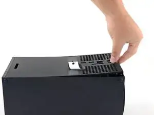
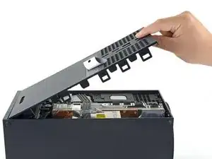
Grip the back panel at the opening you just created and pull it up and away from the shell to unclip the long edges.
-
-
-
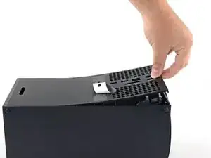
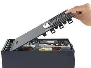
Tilt the back panel up and pull it away from the top edge of the shell to release it from the gap.
-
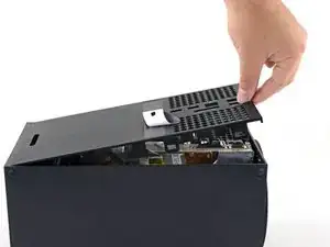
Remove the back panel.
-
-
-
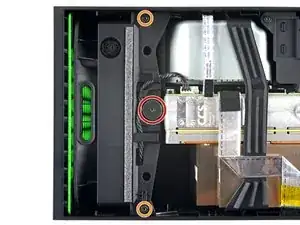
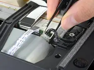
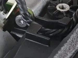
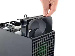
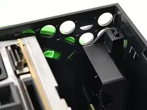
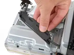
Use a T8 Torx driver to remove the three screws securing the fan to the center chassis:
-
One 10.5 mm pancake screw
-
Two 8.8 mm screws
-
-
-
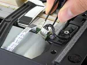
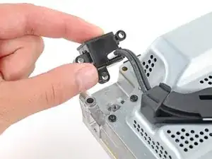
Use your fingers or a pair of blunt tweezers to grip the edges of the fan cable connector, and pull up to disconnect it from the center chassis.
-
-
-
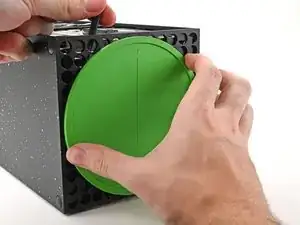
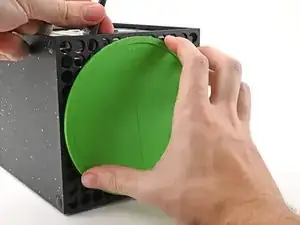
With the locking tab held open, grip the base and rotate it counterclockwise to unlock it from the shell.
-
Remove the base.
-
-
-
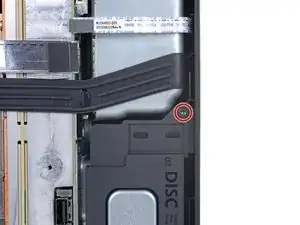
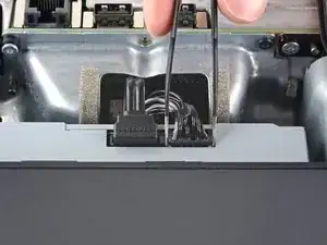
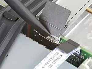
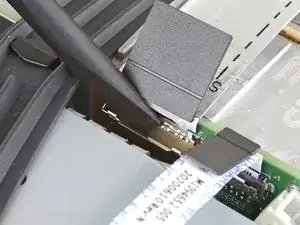
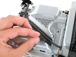
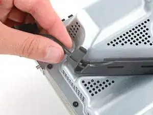
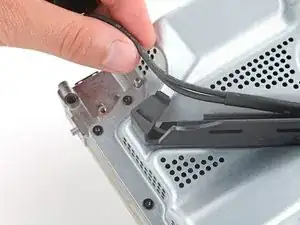
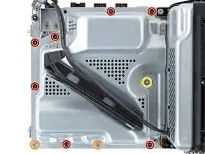
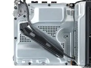
Use a T8 Torx driver to remove the two 8.8 mm screws securing the optical drive's vibration isolator to the shell: one on the base and one on the top of the isolator.
-
-
-
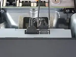
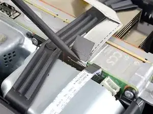
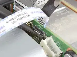
Use a pair of blunt tweezers to grip the edges of the optical drive power connector and pull up to disconnect it from the optical drive.
-
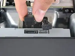
Use your fingers to pull up and disconnect the data cable from the optical drive.
-
-
-
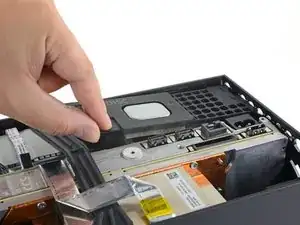
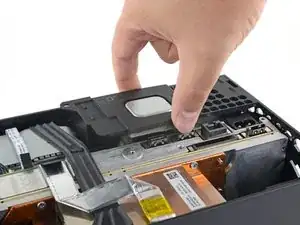
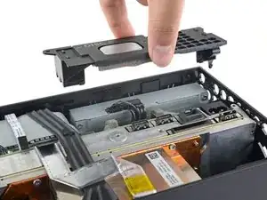
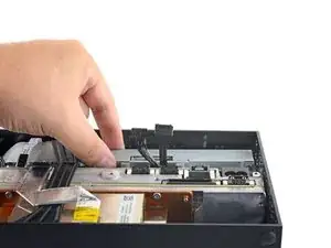
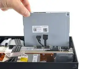
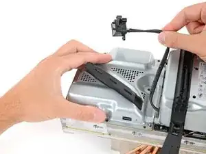
Grip the top edge of the optical drive and pull it out of its slot in the shell to remove it.
-
-
-
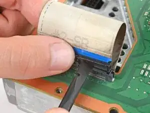
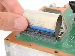
Use the flat end of a spudger to flip open the metal locking tab on the USB port ribbon cable.
-
-
-
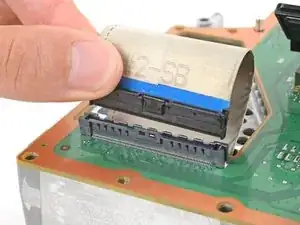
Use a pair of tweezers to pull up on the black plastic pull tab to disconnect the USB port cable.
-
-
-
Use the pointed end of a spudger to depress the metal tab on the side of the power button cable's board connector.
-
With the metal tab depressed, use a pair of tweezers to pull up on the pull tab to disconnect the power button cable from the center chassis.
-
Don't pull on the cable without depressing the metal tab, otherwise you risk damaging either the cable or the connector.
-
-
-
Use a T8 Torx driver to remove the three 7.4 mm screws securing the center chassis assembly to the shell.
-
-
-
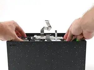
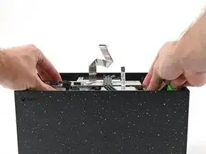
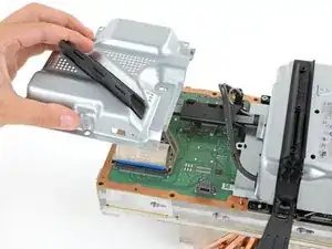
Grip the chassis and pull it towards the top of the shell, uncoupling the guide pegs from the shell.
-
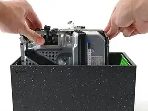
Use two hands to lift out the chassis to remove it from the shell.
-
-
-
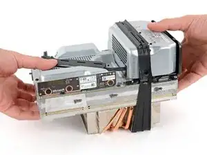
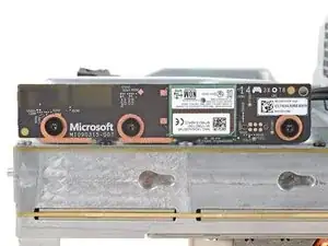
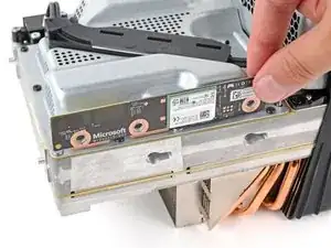
Use a T8 Torx driver to remove the three 9.6 mm‑long screws securing the antenna board to the center chassis.
-
-
-
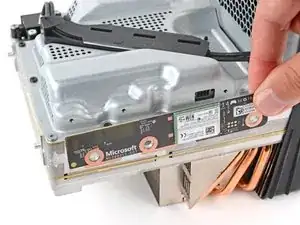
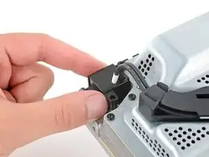
Grip the top right corner of the antenna board and pull it directly away from the center chassis to disconnect it.
-
-
-
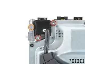
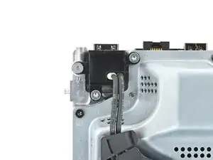
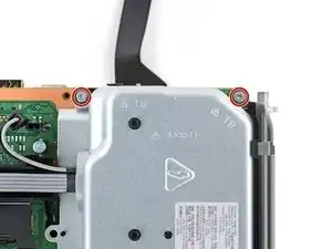
Use a T8 Torx driver to remove the three screws securing the power cable port to the chassis:
-
Two 13.1 mm‑long screws
-
One 35 mm‑long screw
-
-
-
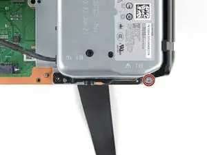
Use a T8 Torx driver to remove the ten screws securing the board shield:
-
Seven 8.7 mm‑long screws
-
Two 35 mm‑long screws
-
One 13 mm‑long screw
-
-
-
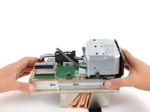
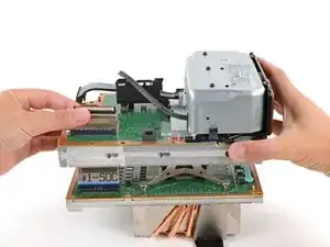
Hold the power supply cable out of the way and lift the board shield straight up to remove it.
-
-
-
Use your fingers to pinch the power supply's 10‑pin power connector, so the locking tab opens outward.
-
With the locking tab open, lift the connector straight up and out of its socket.
-
-
-
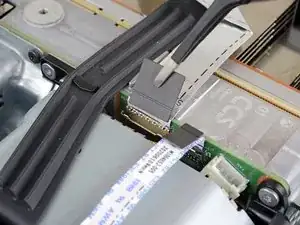
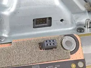
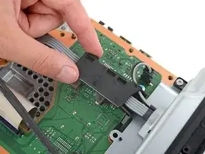
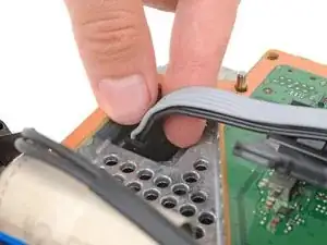
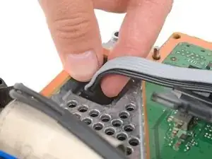
Use your fingers to pinch the locking tab in the center of the interconnect cable connector.
-
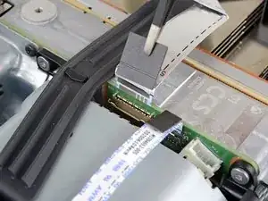
While pinching the tab, insert the flat end of a spudger between the top of the socket and the connector's tab.
-
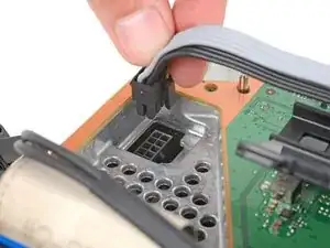
Twist the spudger to lift the connector out of its socket until the clip in the center disengages.
-
-
-
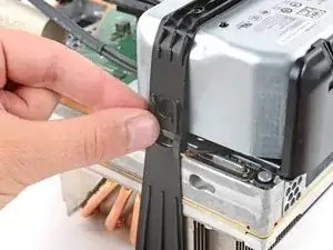
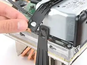
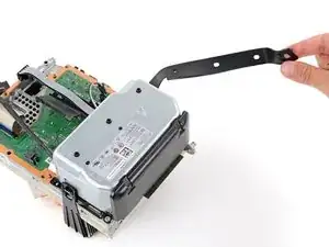
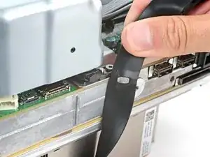
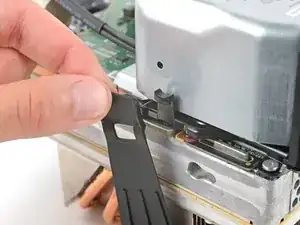
Pull the chassis strap off its three alignment posts and unlatch it from the sides of the power supply.
-
-
-
Use a T8 Torx driver to remove the three 35 mm‑long silver screws from the power supply—leave the fourth black screw in place.
-
-
-
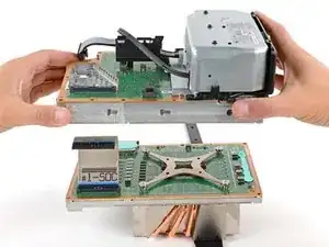
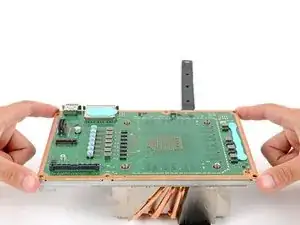
Grip the edges of the center chassis (not the power supply) and lift it off the motherboard and heatsink assembly, routing the interconnect cable through its cutout.
-
-
-
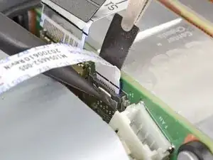
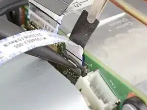
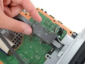
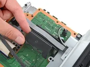
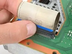
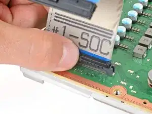
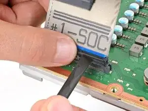
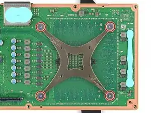
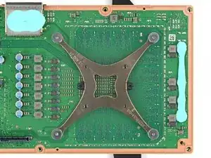
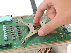
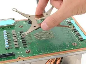
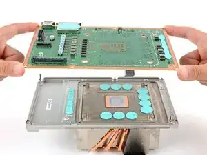
Pinch the locking tab on the interconnect cable on the motherboard and use the flat end of a spudger to disengage the clip.
-
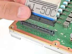
Use your fingers to pull the connector straight up and out of its socket.
-
-
-
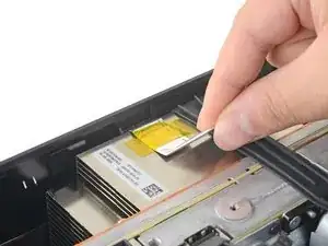
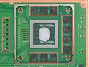
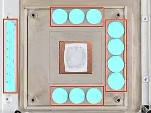
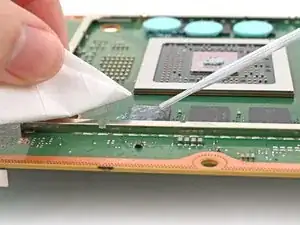
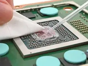
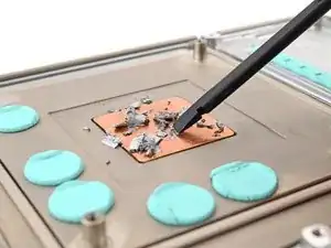
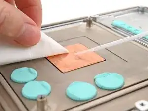
Use isopropyl alcohol (>90%) and a lint-free microfiber cloth to remove any thermal putty residue.
-
-
-
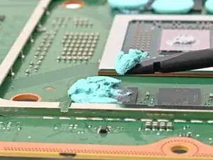
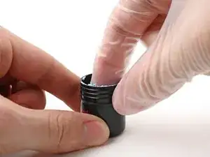
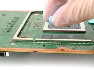
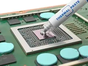
Grab a small piece of thermal putty. Refer to the size of the thermal pad you're replacing for how much you need.
-
-
-
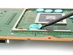
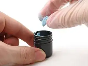
Roll the thermal putty into a ball.
-
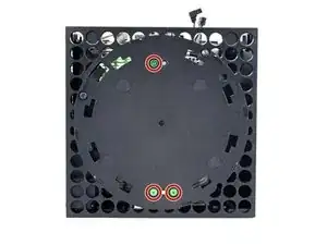
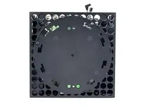
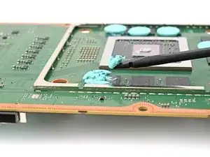
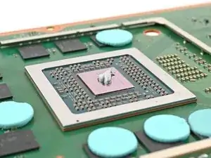
Place the thermal putty where the damaged thermal pad was, making sure it's centered over the component—in this case a memory chip.
-
Optionally, you can use the flat end of a spudger (or an included applicator) to spread the thermal putty over the surface of the component.
-
-
-
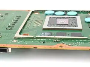
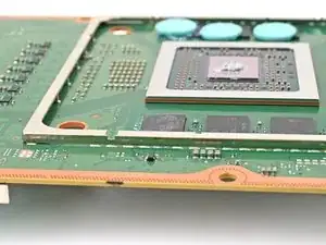
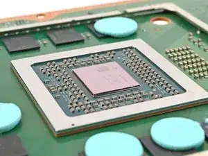
Apply a few drops of isopropyl alcohol (>90%) to the processor and use a coffee filter or a lint-free cloth to wipe away any residue.
-


To reassemble your device, follow these instructions in reverse order.
Take your e-waste to an R2 or e-Stewards certified recycler.
Repair didn’t go as planned? Try some basic troubleshooting, or ask our Answers community for help.