Introduction
Follow this guide to upgrade or replace a broken or cracked display (aka LCD or OLED) on your Lenovo ThinkPad T16 Gen 3 laptop.
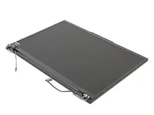
This guide is for the display on its own. If you have an entire screen assembly (including a new top lid, hinges, bezel, and display) follow this guide.
-
-
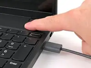
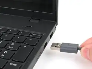
Completely shut down your laptop (don't just put it in sleep mode) and disconnect all cables.
-
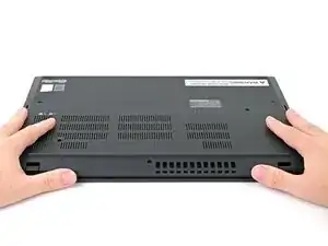
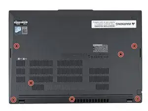
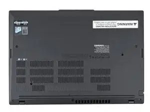
Flip the laptop upside-down, and rotate it so the screen hinge faces towards you.
-
-
-
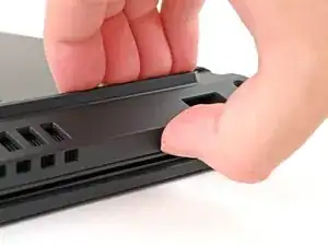
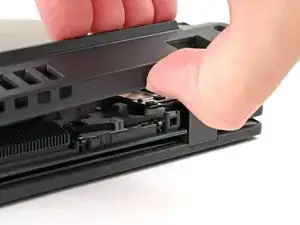
Insert your fingernail or an opening pick into the gap between the base cover and keyboard deck, next to one of the screen hinges.
-
Pry up the base cover until the clips unfasten.
-
-
-
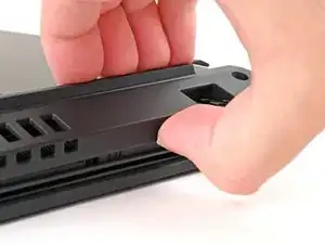
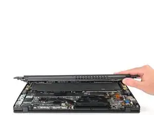
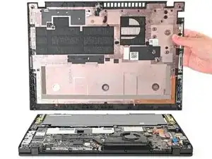
Grasp the base cover along the screen hinge edge and lift slowly to unfasten the remaining clips.
-
Lift and remove the base cover.
-
-
-
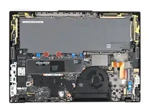
Use a Phillips screwdriver to fully loosen the two captive screws securing the battery connector.
-
-
-
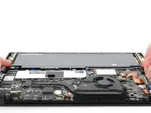
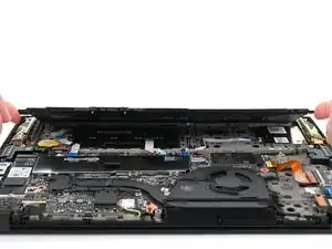
Lift the edge of the battery with the connector to disconnect it.
-
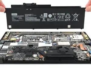
Remove the battery
-
Slide the plastic tabs on the long edge of the battery into their recesses in the frame.
-
Lower the battery into place so the connector goes over its socket.
-
-
-
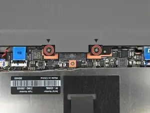
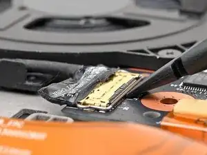
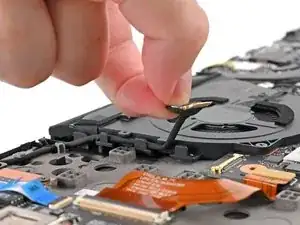
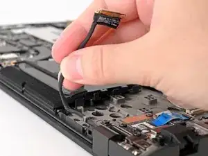
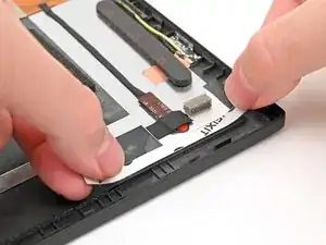
Use the flat end of a spudger or clean fingernail to gently push under the metal buckle of the camera cable connector to unclip it
-
-
-
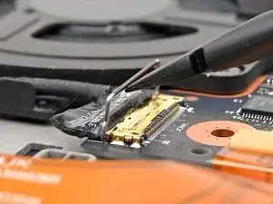
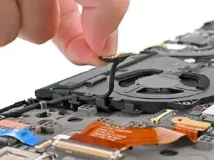
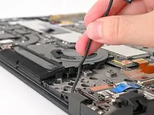
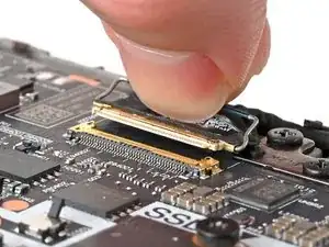
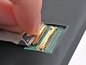
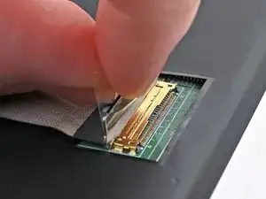
Use a clean fingernail or the flat end of a spudger to gently push under and lift the metal buckle of the display cable connector to unclip it
-
-
-
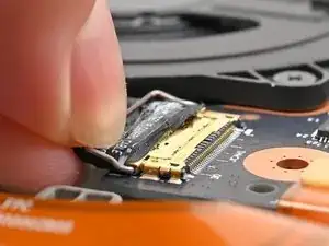
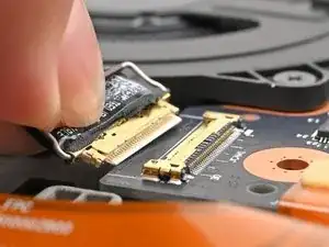
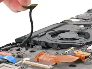
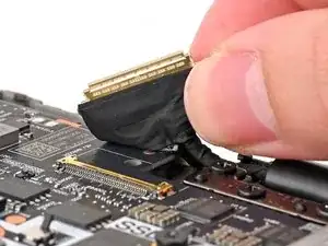
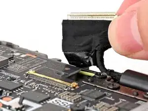
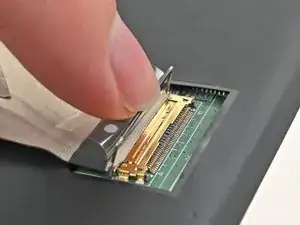
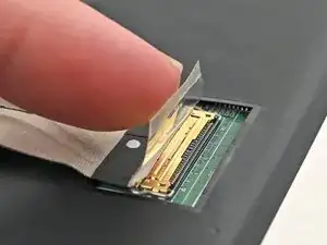
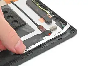
Hold the buckle and cable together and pull it up to separate the adhesive securing the cable to the motherboard.
-
-
-
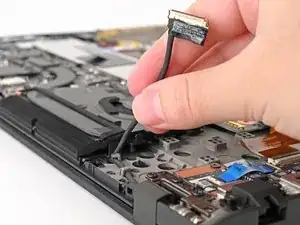
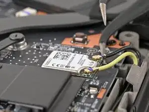
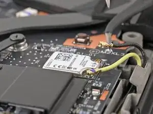
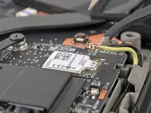
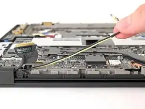
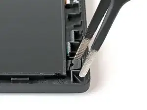
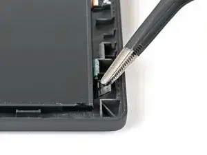
Insert an arm of your angled tweezers under the metal neck of one of the coaxial connectors on the Wi-Fi card and lift straight up to disconnect it.
-
Repeat for the other connector.
-
-
-
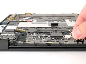
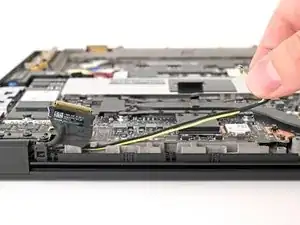
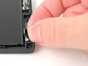
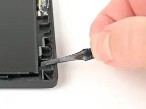
Grab both Wi-Fi antenna cables and guide them out of their clips on the frame until they're only attached to your laptop at the hinge.
-
-
-
Open your laptop 180 degrees (so it's completely flat) and lay it keyboard side down on your work surface.
-
-
-
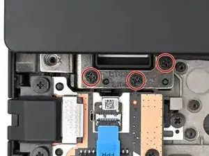
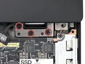
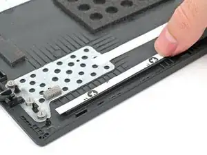
Use a Phillips screwdriver to remove the six 6.5 mm‑long screws securing the hinges to the laptop.
-
-
-
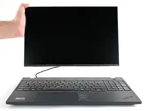
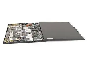
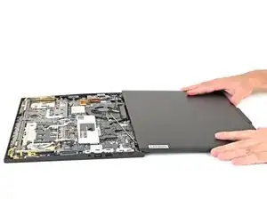
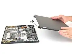
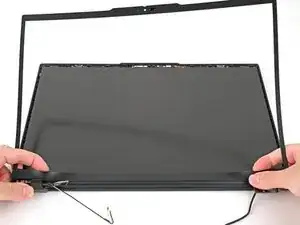
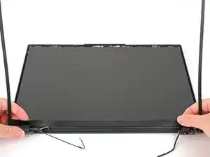
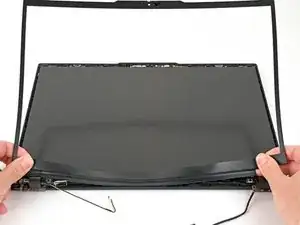
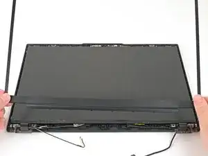
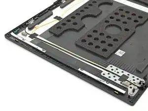
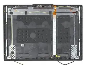
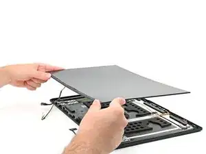
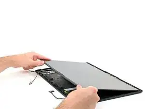
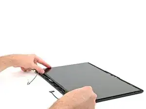
Lift the screen assembly straight up and remove it from the laptop.
-
Make sure the screen hinges are open 180 degrees and guide them into their recesses in the frame.
-
Install and partially tighten the four hinge screws.
-
Close your laptop and make sure the screen is properly aligned. If it clicks or snaps, readjust the alignment.
-
Fully tighten the hinge screws.
-
-
-
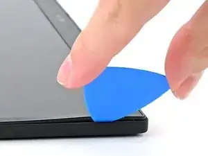
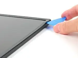
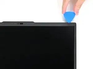
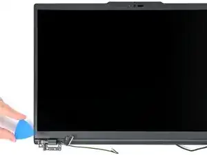
Insert the tip of an opening pick at a downward angle between the bezel and screen assembly, near the top right corner.
-
Lower the pick so it's flat with the screen and the tip is under the screen bezel.
-
-
-
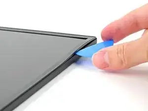
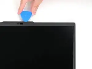
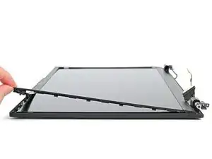
Re-insert your opening pick near the top right corner.
-
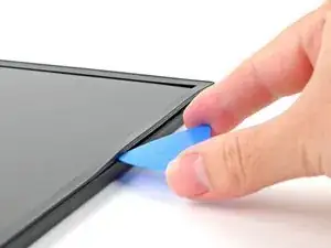
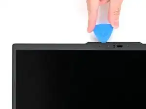
Slide your opening pick around the top right corner to unfasten the frame clips, stopping before you hit the webcam.
-
Remove the opening pick.
-
-
-
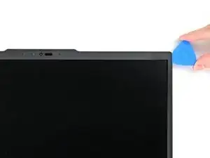
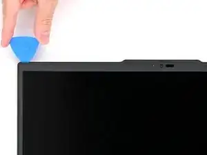
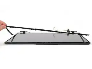
Re-insert your pick to the left of the webcam and slide it towards the top left corner and down the left edge to unfasten the remaining clips.
-
-
-
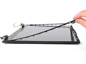
Gently lift the bezel on the right, top, and left edge to ensure all the clips are fully unfastened.
-
-
-
Use your fingers to slowly peel the bottom edge of the bezel from the protective film on the display.
-
-
-
Once the adhesive is completely separated, lift the bottom edge of the bezel straight up to unfasten its clips.
-
Remove the bezel.
-
-
-
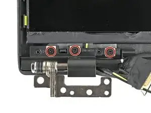
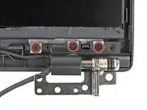
Use a Phillips screwdriver to remove the six 3.75 mm‑long screws securing the hinges (3 in each).
-
-
-
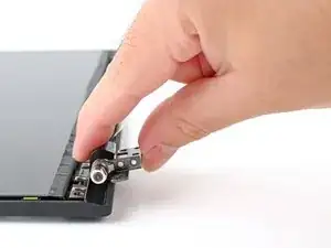
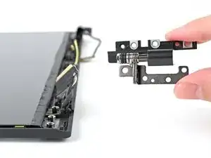
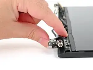
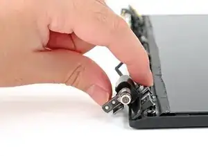
Use your fingers to rotate one of the hinges downwards to unfasten the clips holding it in place.
-
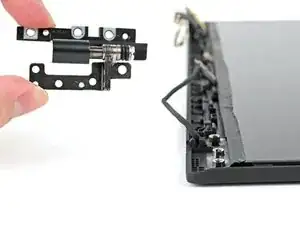
Remove the hinge from its recess
-
-
-
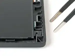
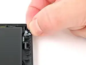
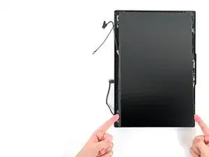
Use tweezers or your fingernails to grab one of the pull tabs, located at the top left and right corners on top of the display.
-
-
-
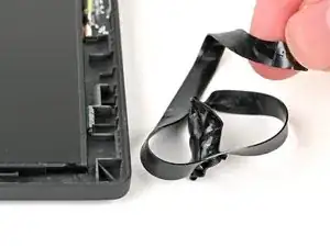
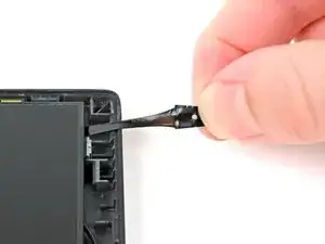
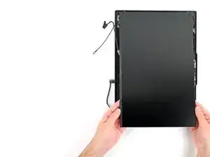
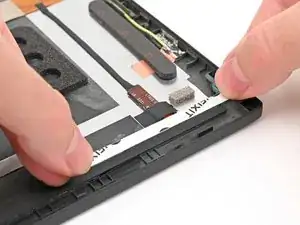
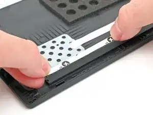
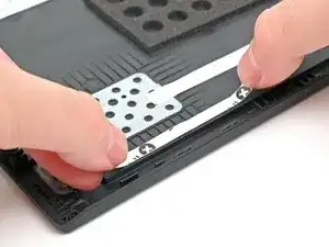
Use your fingers to grasp the black pull-tab on the adhesive strip.
-
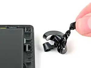
Pull the strip out slowly and steadily at a low angle. Keep pulling until it is completely removed from beneath the display.
-
-
-
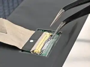
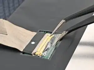
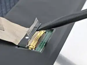
Insert angled tweezers underneath the tape securing the eDP connector to the back of the display.
-
Peel up the tape until it is only attached to the cable.
-
-
-
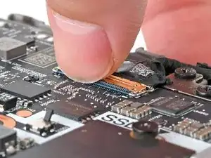
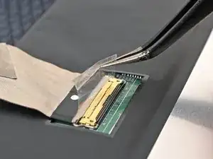
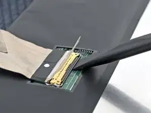
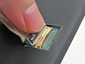
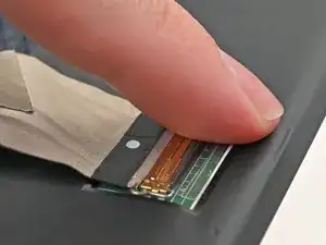
Use a clean fingernail or the flat end of a spudger to lift and unlatch the metal buckle on the display cable connector.
-
-
-
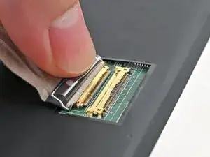
Grab the buckle and cable together and gently pull the connector straight out of its socket.
-
-
-
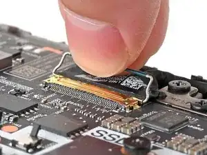
Grip the display cable and buckle together and insert the connector fully into the new display's socket.
-
-
-
Flip the buckle over the socket and use a clean finger or spudger to press the buckle down until it clicks into place.
-
-
-
Use a clean finger to press the tape down over the socket until it adheres to the back of the display.
-
-
-
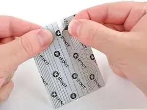
Align the adhesive strip with the cut-out in the chassis where the old pull tab was.
-
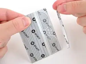
Apply the top end first, then use a finger or the flat end of a spudger to smooth the rest of the strip as you lay it down, squeezing out any air bubbles.
-
-
-
Repeat this process for the bottom adhesive strip, leaving an overhang at the bottom edge for future maintenance.
-
-
-
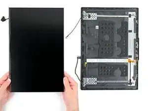
Align your replacement display with the laptop.
-
Place the top edge down first, ensuring it is centered. You may have to wiggle it before it settles into place.
-
Lay the display down fully.
-


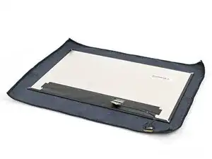
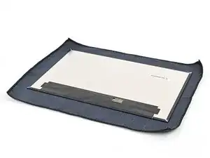


Compare your new replacement part to the original part—you may need to transfer remaining components or remove adhesive backings from the new part before you install it.
To reassemble your device, follow these instructions in reverse order, beginning from Step 29.
Take your e-waste to an R2 or e-Stewards certified recycler.
Repair didn’t go as planned? Try some basic troubleshooting, or ask our Answers community for help.