Introduction

  1. lgs2BFmwctNUvEEY
    • Push down on the screw to depress the spring loaded hinge and release the door.

  2. xqMOa4QfTrEMSjLQ
    • Remove six 5.3 mm #00 screws.

    • Remove one 3.4 mm #00 screw.

    • The short screw has a machine thread and screws into the plate underneath. The rest screw into the plastic body.

  3. JBNm1gvrrVIsOnvC
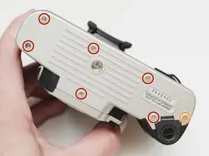
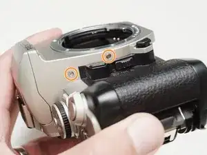
    • Remove three 5.3 mm #00 screws (the bottom-most screw is not always present).

    • Remove one 7.3 mm #00 screw.

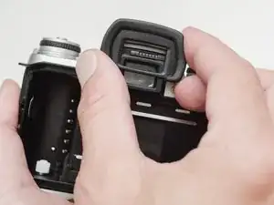
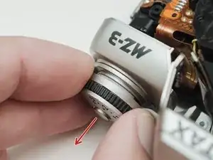
    • Remove the remote trigger cover.

  4. kaurbKcGc3sICMvp
    kaurbKcGc3sICMvp
    qAMWaUYPEdKSqKBQ
    • Remove one 3.4 mm #00 screw.

    • Remove two 5.3 mm #00 screw.

    • Gently lift up on the flash housing to help remove the cover if necessary.

  5. XTT2gETZspMWvdLW
    • Remove two 3.9 mm #00 screws.

  6. ARa5irnNBe4saLjG
    • Slide the eye cup up and off to access the screws underneath.

  7. WXSxikGQnRIdBm53
    WXSxikGQnRIdBm53
    dYUQ2h3O4Uup2OHy
    ScUMgBowkxHStFqJ
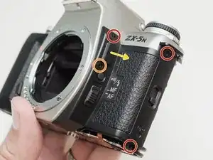
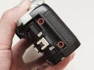
    • Remove two 5.3 mm #00 screws by the eyepiece.

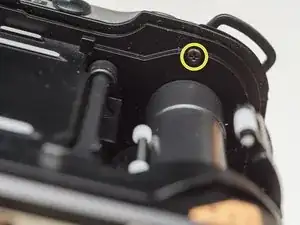
    • Remove one 6.8 mm #00 screw in the battery compartment.

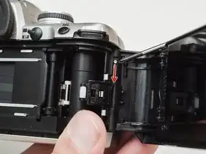
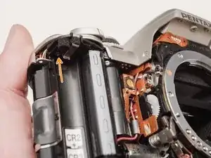
    • Remove one 7.0 mm #00 screw near the take up spool.

  8. 1w4wgSUjvi2VyATp
    • Lift the cover so it is just free of the body. It is still attached by several wires.

  9. UYOb45jluXTBh2EH
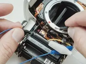
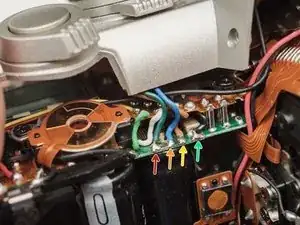
    • Use a 1kΩ-10kΩ resistor to discharge the capacitor. Place the resistor between the blue wire, exposed in the previous step, and ground.

    • The flash capacitors store energy at a very high voltage. Failing to discharge the capacitors properly could result in personal injury and/or damage to the camera.

  10. aldFfVMXX1eCBqkS
    • Unsolder one green wire.

    • Unsolder one blue wire.

    • Unsolder one brown wire.

    • Unsolder one black wire.

  11. 3ePHgPVX2WpknD6R
    3ePHgPVX2WpknD6R
    6ygxoCAYVRGEJBiX
    fnEtfvDRFEDU16AV
    • Unsolder one black wire.

    • Pull black wire out from its routed location.

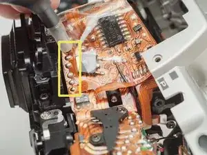
    • Unsolder flex connector

    • Be careful not to overheat the flex circuit. Work in short durations. Allow for cool downs in between if necessary.

    • Some repairs can be performed with the top cover still connected but the flex connection is fragile and easily damaged.

  12. EsnEpNQIAYn2eDRr
    • Set the exposure compensation dial to '0'.

  13. w2yObYxGlUxMrJAC
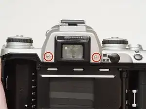
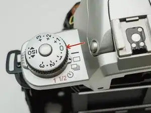
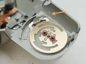
    • Remove two #00 screws

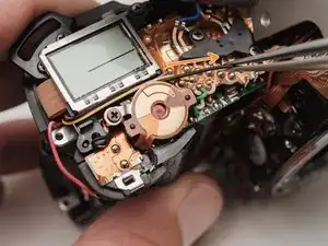
    • Be careful not to damage the feeler contacts from the drive mode switch throughout the repair. There are delicate and easily bent.

  14. hkwYDMNBDx1CwRPK
    hkwYDMNBDx1CwRPK
    AHYEDiQ1Dj4OrJxf
    • Remove the contact PCB.

    • There is a metal plate underneath that may stick to the PCB.

  15. Mu2VkRB6vYLupmfa
    • Slide the exposure compensation dial out of the top cover.

    • If the dial was not set to '0' in Step 10, the knob will not slide out. Turning the knob at this stage could damage the detent spring.

  16. xIiiaRTRlN2BYec2
    xIiiaRTRlN2BYec2
    dZxHMZFGZwLDgauy
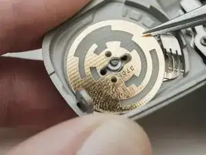
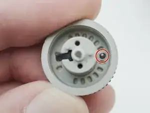
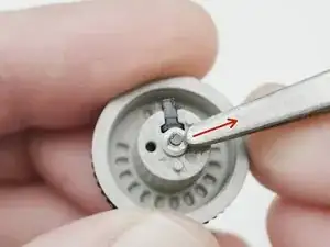
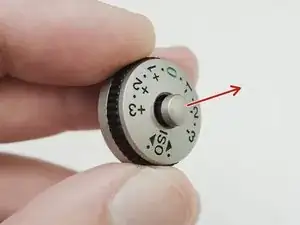
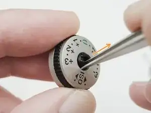
    • Remove the ball bearing from the inside of the dial.

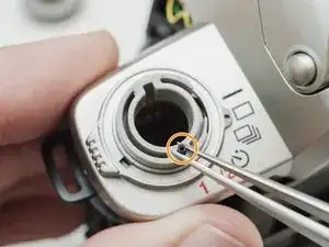
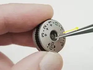
    • Remove the detent spring from the top cover.

  17. KpneVa2UHLTKPEW4
    • Remove the small plastic c-clip on the end of the shaft.

    • Place your finger over the c-clip whenever you are working with it to prevent it from unexpectedly flying away.

  18. lERuDwrF6ISbvrbX
    lERuDwrF6ISbvrbX
    gIRatORRo6dXWOgt
    KeNYB6loqWHLiuvy
    • Remove the lock button.

    • Remove the lock actuator.

    • Remove the lock spring.

  19. hnkAorMMk5JxNSWF
    hnkAorMMk5JxNSWF
    iP2FrLtOHfINmQFX
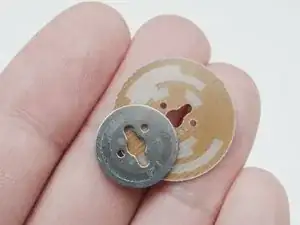
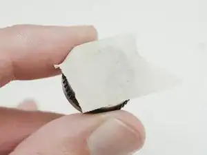
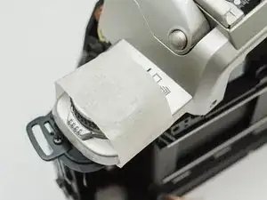
    • Use tape to hold components in place when reassembling the lock button and installing the dial.

Conclusion

To reassemble your device, follow these instructions in reverse order.

Sam Gustafson

Member since: 02/09/22

7682 Reputation

0 comments