Introduction
The process of replacing the motherboard on the TOZO HT2 headphones is quite intricate due to the delicate handling and soldering involved in this particular task. It is essential to exercise caution and precision in this replacement to ensure that the headphones function properly after the new motherboard is installed. Once you have confirmed that the motherboard is the component requiring replacement, you can refer to this guide that outlines the procedure for replacing the motherboard. The motherboard is positioned beneath the right ear pad of the headphones. Notably, these headphones are equipped with two distinct circuit boards, and this detailed guide is specifically designed to assist you in replacing the circuit board located within the right ear pad. By carefully following the instructions provided in this guide, you can confidently navigate through the motherboard replacement process, ensuring that your TOZO HT2 headphones are restored to optimal working condition.
Each of the screws for this project are the same 6.3mm Phillips head screws.
-
-
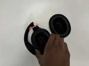
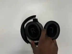
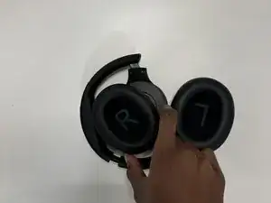
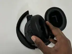
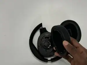
Firmly hold the headphone housing in one hand to hold the device steady and put the other hand on the ear pad you intend to replace.
-
-
-
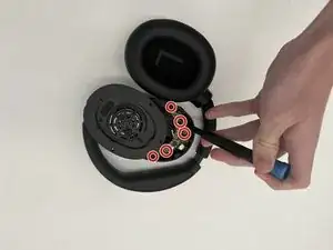
Use a Phillips screwdriver to remove each of the four screws on the speaker cover.
-
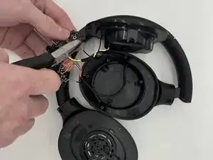
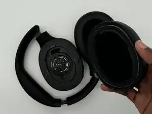
Lift the cover off without pulling on the wires inside and set it to the side to access the circuit board.
-
-
-
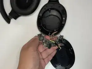
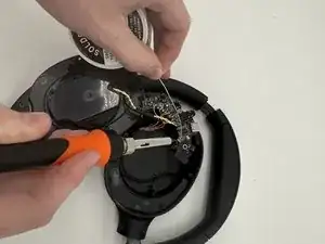
Use a Philips screwdriver to remove the screws that secure the main board.
-
Carefully lift the board out of the headphones, making sure to not pull on and damage the wires inside.
-


To reassemble your device, follow the above steps in reverse order.
Take your e-waste to an R2 or e-Stewards certified recycler.
Repair didn’t go as planned? Try some basic troubleshooting or ask our Answers community for help.

This info was really useful, and helped me to investigate why the left speaker didn't work - sadly it appears to be a break in the wiring from right to left sides (the grey wire in the bundle - if I jumper it, I get sound, but I'm not sure if I can replace the whole cable bundle or somehow pull just one wire.....). The 90 degree bends where the wire enters each shell from the headband is a bad idea.
CCB -