Introduction

Use this guide to replace the motherboard in your Xbox Series X (Digital Edition) gaming console.

You can also use this guide to clean and reapply thermal paste in your Xbox.

Before you begin, completely power down and unplug all cables from your console. Remember to follow general electrostatic discharge (ESD) safety procedures while repairing your console.

  1. AypelPgoTxaJoKFD
    AypelPgoTxaJoKFD
    KBWiDZuUDl4RA3uo
    • Before you begin, completely power down and unplug all cables from your console.

    • Two stickers cover the back panel screws. You can remove the stickers without heating them, though it makes them much easier to remove cleanly.

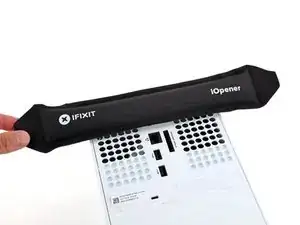
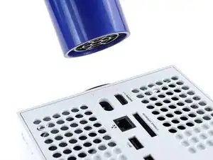
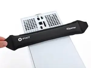
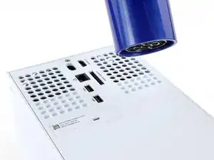
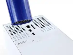
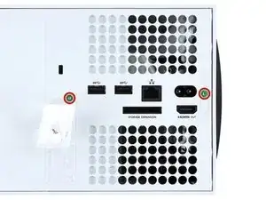
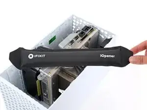
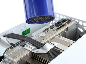
    • Heat an iOpener and lay it on the smaller sticker near the bottom of the back panel for two minutes.

    • Alternatively, you can use a hair dryer to heat the sticker.

  2. v1dUpQQS2lYRLUsH
    v1dUpQQS2lYRLUsH
    NdNRckQLBpYFQ61D
    31oUFi4UvURQcjXq
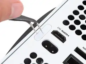
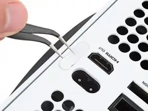
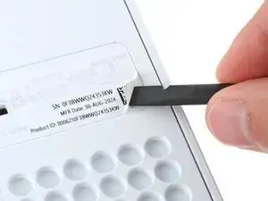
    • Use a pair of angled tweezers to remove the sticker hiding the first screw on the back panel, near the base.

  3. nemuGwbC1YIXKi66
    nemuGwbC1YIXKi66
    O1eLVGlYtZKcUcXP
    CybW5HMbXROJs2KC
    • Use an iOpener or hair dryer to heat the larger sticker near the center of the back panel.

  4. AcTPiFLqqo4HCDDk
    AcTPiFLqqo4HCDDk
    MWiWBWw3sVFtUcAl
    L2Wo6IJA3FaCf24P
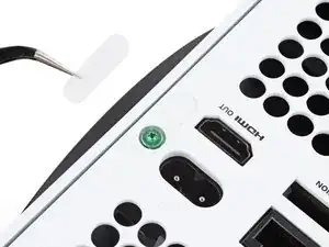
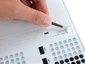
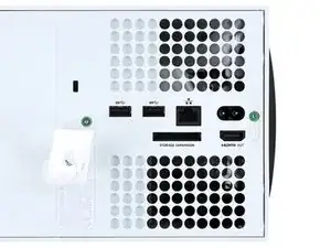
    • Use the flat end of a spudger to scrape up a corner of the larger sticker until you can grip it with a pair of blunt tweezers.

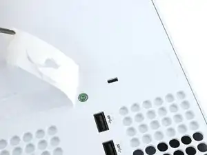
    • Use blunt tweezers to peel back the sticker to reveal the second screw.

    • You only need to peel this sticker to where you can access the hidden screw. You don't need to pull it completely off.

    • Technically, these are tamper-evident stickers, but don't worry—Microsoft can't legally void your warranty, as long as you don't damage anything. Have fun!

  5. sfZXSBU5uaVytGCV
    sfZXSBU5uaVytGCV
    GYYYlm1IAdKDHBJw
    • Throughout this repair, keep track of each screw and make sure it goes back exactly where it came from to avoid damaging your console.

    • Use a T8 Torx driver to remove the two 7.4 mm‑long screws securing the back panel.

  6. FDxR4GKjpo2HjiLo
    FDxR4GKjpo2HjiLo
    xuBkTmX4myZlb2fR
    jYXiT5eNXiDEHkqO
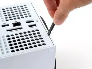
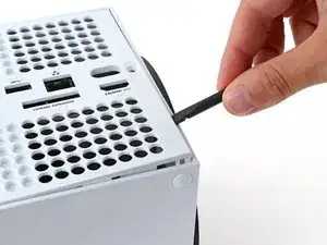
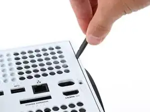
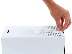
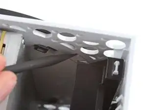
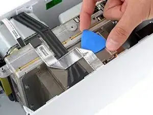
    • Insert the flat end of a spudger into the gap between the back panel and the shell, near the left side of the base.

    • Pry up the back panel to release it from the locking clips.

  7. NLuvivjpUaQttKDs
    NLuvivjpUaQttKDs
    glqOhiOkIMunabBR
    xSlNfvUnBDAYtVuy
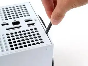
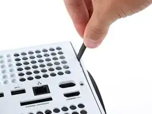
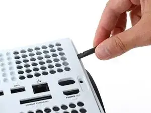
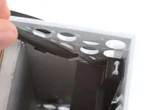
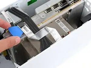
    • Insert the flat end of a spudger into the gap between the back panel and the shell, near the right side of the base.

    • Pry up the back panel to release it from the locking clips.

  8. raEhJf4j2JANGjUA
    raEhJf4j2JANGjUA
    32vpOrKlSKiiVUtI
    rJTbeew1aHSNj3Xv
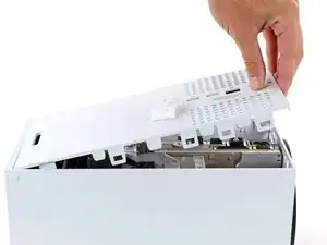
    • Grip the back panel at the opening you just created and pull it up and away from the shell to unclip the long edges.

    • During reassembly, press along the edges of the back panel to snap it into place.

  9. xGEgfdsnC5tVhFJR
    xGEgfdsnC5tVhFJR
    rjEGrstSYJdOd4Jo
    fXODEtKZ1v4wrFv5
    • The back panel slots into a gap at the top of the shell.

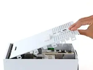
    • Tilt the back panel up and pull it away from the top edge of the shell to release it from the gap.

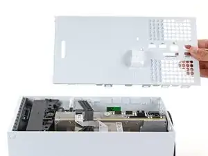
    • Remove the back panel.

  10. MPn4ah3bCZ1yWKh6
    MPn4ah3bCZ1yWKh6
    6sgE3f5LenMyJxPP
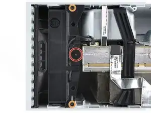
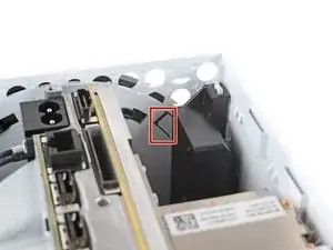
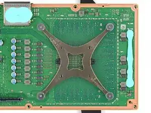
    • Use a T8 Torx driver to remove the three screws securing the fan to the center chassis:

    • One 10.3 mm‑long pancake screw

    • Two 9 mm‑long screws

  11. 6PffkpqSeHgZbNP2
    6PffkpqSeHgZbNP2
    SGxpn2kGptsFojbq
    vgIxTrICJRbnfqr2
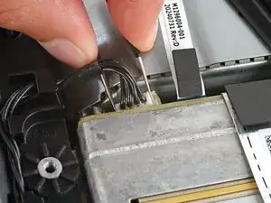
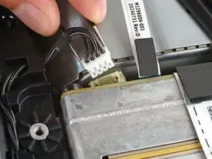
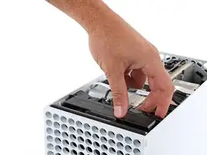
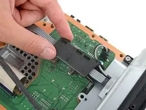
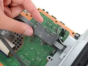
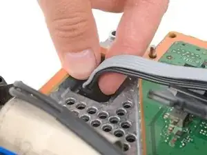
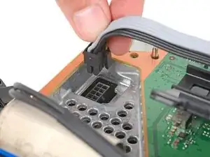
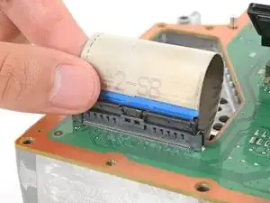
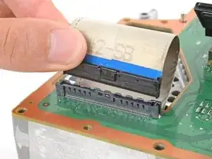
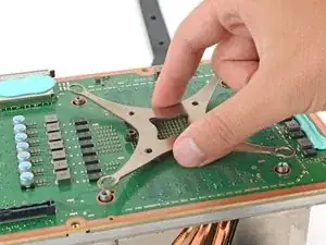
    • Use your fingernails or a pair of angled tweezers to firmly grip the edges of the fan cable connector.

    • Grip your tweezers close the connector to get a better grip.

    • Pull the connector straight out of the socket to disconnect it.

    • If you're having trouble, gently rock the connector side to side to loosen it.

    • Always pull cables by their connectors and not the wires themselves.

    • During reassembly, route the fan cable underneath its small cable guide on the fan housing so it doesn't interfere with the back panel.

  12. XQyZlR4cxMHjoGYx
    XQyZlR4cxMHjoGYx
    4Ko4B5a52LGmHPTU
    5YKemIevYGVQlJPT
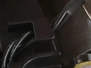
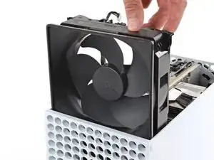
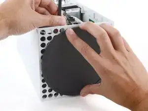
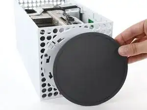
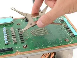
    • Slide the fan out of its slot to remove it.

    • During reassembly:

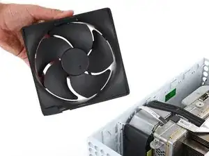
    • Before installing the fan, make sure it's clean! Use a dust blower or compressed air to blow off any dust or debris, and wipe the fan clean with a clean cloth.

    • Use a finger to keep the fan blades steady—it makes them easier to clean.

    • Note that the fan can only be installed one way—make sure Master Chief is facing you.

  13. q2IjeBcCiqngZVmC
    q2IjeBcCiqngZVmC
    PSNU41LBk2EQFy6h
    KaX1PCOwa4vmE5V3
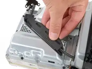
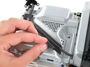
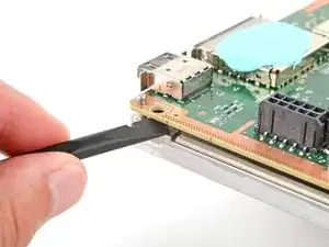
    • Use the flat end of a spudger to pry up the locking tab holding the base to the shell.

    • Keep the locking tab held open for the next step.

  14. rJtyV5W2NHU2B1JM
    rJtyV5W2NHU2B1JM
    66KXLCGWJ6CxJ2op
    aPdFxgVqAKbHN4cM
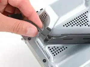
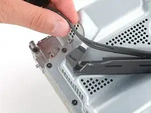
    • With the locking tab held open, grip the base and rotate it counterclockwise to unlock it from the shell.

    • Remove the base.

    • During reassembly, put the base tabs into their holes on the shell and twist clockwise until the base snaps into the interior locking tab.

    • When locked in place, the Hello from Seattle line will be parallel with the device's sides.

  15. NeKUM2qvcQQVBHJJ
    NeKUM2qvcQQVBHJJ
    P2LeNqUV6RRYpXcU
    M6GqHbshyaRYaEDj
    • The ribbon cables and their connectors are extremely fragile, so always open locking tabs gently and pull cables slowly.

    • Use a spudger to flip open the metal locking tab on the USB port ribbon cable.

    • During reassembly, gently snap the metal locking tab back into place once the cable has been inserted.

  16. GOmZT2eVDdlKkB2I
    GOmZT2eVDdlKkB2I
    6PHosomvtSYWSayL
    yOPyxPLEC4vpHgFD
    • The USB port cable is secured to the chassis with two pieces of mild adhesive.

    • Use an iOpener or a hair dryer to heat the USB port cable.

  17. ZCkD63XIwjldOj1v
    ZCkD63XIwjldOj1v
    NpeCgrhqBrrZpFB1
    WcH6vDHlhMxk2Cnl
    • Slide an opening pick under the USB port cable to separate the adhesive securing it.

    • During reassembly, use thin double‑sided adhesive to secure the cable. If there's adhesive left and it's still sticky, you can reuse it. If you have a new cable, check it for pre‑installed adhesive and remove any liners.

  18. IUrTYmFqEgufqVOU
    IUrTYmFqEgufqVOU
    LvAP1UVRBLQEcJda
    cuKWg24u2HTDBfB2
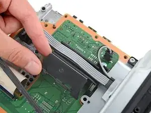
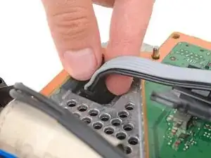
    • Use a pair of tweezers to gently pull up on the black plastic pull tab to disconnect the USB port cable.

    • Pull only on the pull tab, not the cable itself.

    • Move the USB port cable out of the way of the chassis.

  19. DMIaBGOtoPPGNGHD
    DMIaBGOtoPPGNGHD
    HoOQqRfBAieYJN2R
    SnsY64eWouKrZuXQ
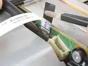
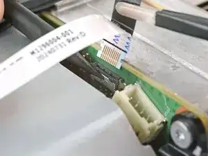
    • Use the pointed end of a spudger to depress the metal tab on the side of the power button cable's board connector.

    • With the metal tab depressed, use a pair of tweezers to pull up on the pull tab to disconnect the power button cable from the center chassis.

    • Pull only on the pull tab, not the cable itself.

    • Don't pull on the cable without depressing the metal tab, otherwise you risk damaging either the cable or the connector.

    • During reassembly, the cable should lightly "snap" into place when inserted.

  20. FeRCKSUSYmcDEaca
    FeRCKSUSYmcDEaca
    VMBvSXHZmiBbxVuC
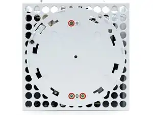
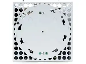
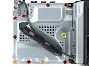
    • Use a T8 Torx driver to remove the three 7.4 mm‑long green screws securing the center chassis assembly to the shell.

  21. G5fXpkuI4BGkkQOR
    G5fXpkuI4BGkkQOR
    dENPOhBCp1VNtDD3
    QANxVvcldCkucVOZ
    • The center chassis assembly is aligned to the bottom of the shell with guide pegs. These pegs will need to slide out of their slots to allow the chassis to be lifted out.

    • Grip the chassis and pull it towards the top of the shell, uncoupling the guide pegs from the shell.

    • Use two hands to lift out the chassis to remove it from the shell.

    • During reassembly:

    • Make sure neither of the ribbon cables get pinched as you lower the center chassis into the shell.

    • Use the alignment pegs and cutouts to properly orient the chassis in the shell:

    • Two pegs on the chassis with cutouts on the bottom of the shell.

    • Three pegs in the shell with cutouts on the chassis.

  22. dkJWbTlLhb2VtF24
    dkJWbTlLhb2VtF24
    YhJWxpLjQb3ICtBE
    • Gently place the chassis heatsink-side down on a clean work surface.

    • During reassembly, this is a good point to clean the heatsink fins of any dust, dirt, or debris that may have built up over time. Use a dust blower or compressed air to clear out the fins.

  23. bCZlVYbCeYWLNPO2
    bCZlVYbCeYWLNPO2
    kfqk4xAQRFf3WC4j
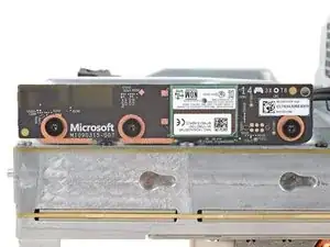
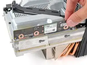
    • Use a T8 Torx driver to remove the three 9.6 mm‑long screws securing the antenna board to the center chassis.

  24. TbTnEVunHMgXVtjx
    TbTnEVunHMgXVtjx
    aXOggJBCMXbrCNkG
    QjLFK6kKIELBRB2b
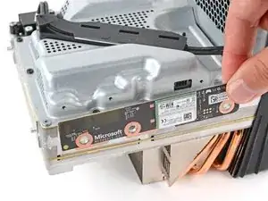
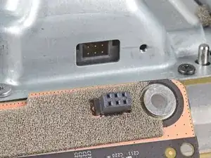
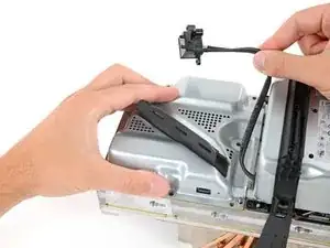
    • Grip the top right corner of the antenna board and pull it directly away from the center chassis to disconnect it.

    • During reassembly, align the board's connector with the port on the center chassis and press to reconnect.

  25. KrZfXIlegalLQXyn
    KrZfXIlegalLQXyn
    chkBWKxwllEUUWjo
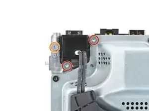
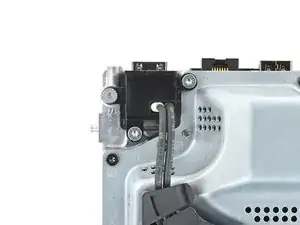
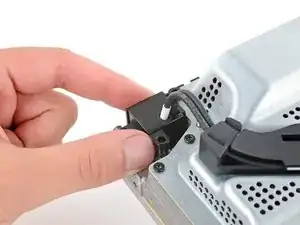
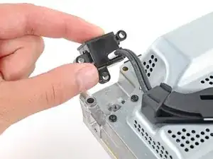
    • Use a T8 Torx driver to remove the three screws securing the power cable port to the chassis:

    • Two 13.1 mm‑long screws

    • One 35 mm‑long screw

  26. eRwtodYRaX5SFkfW
    eRwtodYRaX5SFkfW
    MFnfRXMWAHmWQsBZ
    • Lift the power connector out of its recess in the chassis.

  27. I2ADIyVhLoi2H1Ss
    I2ADIyVhLoi2H1Ss
    Ud2YtfstA3MWGiAI
    • Unlatch and open the lid on the power cable's plastic guide.

  28. s2jx6QE5UZVqCnu6
    s2jx6QE5UZVqCnu6
    y2jVnvSFTRZpPIoQ
    • Lift the power cable out from underneath the extra section of the cable guide.

  29. kdVNQWjXWQeNxtT6
    kdVNQWjXWQeNxtT6
    TJQAUdAyqmDvBbKX
    • Use a T8 Torx driver to remove the ten screws securing the board shield:

    • Seven 8.7 mm‑long screws

    • Two 35 mm‑long screws

    • These screws are very tight and may take significant force to loosen.

    • One 13 mm‑long screw

  30. yqHbnGMZjC6auQF3
    yqHbnGMZjC6auQF3
    qeGZEiixDEY2U1LJ
    QIBDSiDUcVF1BKwD
    • Hold the power supply cable out of the way and lift the board shield straight up to remove it.

  31. BPNcB2uISAxWkKGf
    BPNcB2uISAxWkKGf
    SNVJBfMxtqppSFPQ
    NjvUALiQgNaXZPd6
    • Open the lid on the power supply's plastic cable guide.

  32. yphNrtYlV6jNKvQB
    yphNrtYlV6jNKvQB
    HNfR3MstEpkFNdNa
    xCQdcmU3kGwKrZBD
    • Always pull cables by their connectors and not the wires themselves.

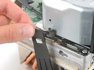
    • Use your fingers to pinch the power supply's 10‑pin power connector, so the locking tab opens outward.

    • With the locking tab open, lift the connector straight up and out of its socket.

  33. 5AadbMnQLNVLg5KQ
    5AadbMnQLNVLg5KQ
    KQamkKnxEvW64rLA
    Mb1gWmOkbGaTkh6g
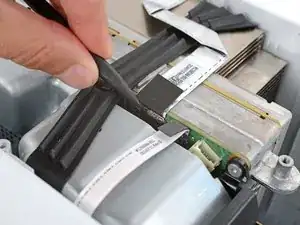
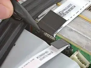
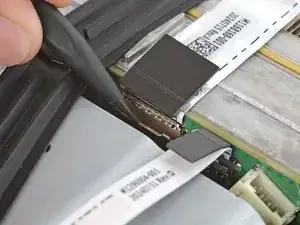
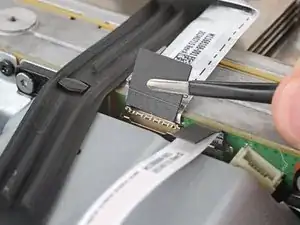
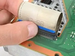
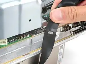
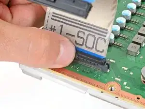
    • Use your fingers to pinch the locking tab in the center of the interconnect cable connector.

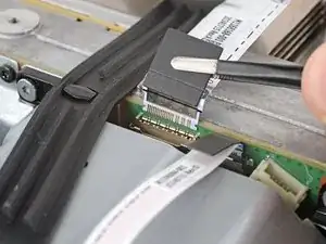
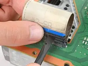
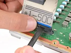
    • While pinching the tab, insert the flat end of a spudger between the top of the socket and the connector's tab.

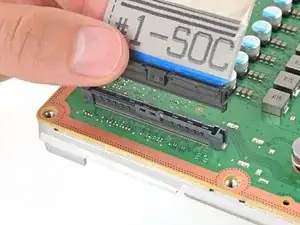
    • Twist the spudger to lift the connector out of its socket until the clip in the center disengages.

  34. fdEcpUaZyEv1Tviq
    fdEcpUaZyEv1Tviq
    bZWfKrTkJQKXQn2o
    • Use your fingers to pull the connector straight up and out of its socket.

    • During reassembly, insert the interconnect cable connector into its socket and press down on both edges until the connector snaps into place.

  35. yZkvSmUAAHyZJrZN
    yZkvSmUAAHyZJrZN
    hVZeweTikMqvmXuF
    kLtOsaTQCQEpiQOJ
    • Pull the rubber strap down and away from the chassis to unlatch it.

  36. tcBGkZOpywZrMlI4
    tcBGkZOpywZrMlI4
    mAypsisTMYrVWu6F
    NomCqUBbH3EuOJQM
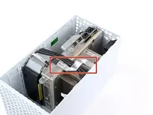
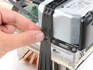
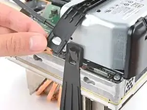
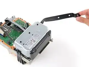
    • Pull the chassis strap off its three alignment posts and unlatch it from the sides of the power supply.

    • You can leave the strap under the chassis or remove it.

    • During reassembly, make sure the nubs in the middle of the strap go unto their cutouts on the heat sink fins.

  37. lK4EeuTQYlUgeaCt
    lK4EeuTQYlUgeaCt
    ZGqwDrBHAeSGjH6g
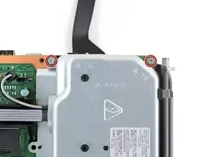
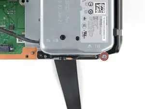
    • Use a T8 Torx driver to remove the three 35 mm‑long silver screws from the power supply—leave the fourth black screw in place.

  38. dXwC4CjJbeuuyLxh
    dXwC4CjJbeuuyLxh
    ZslNcbnnQjctZvAP
    KFFhIrwZWGQctDfs
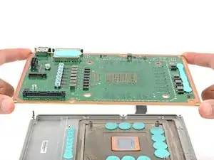
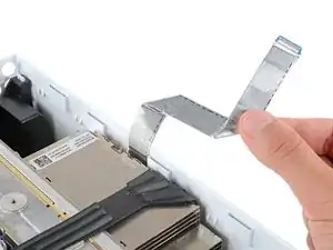
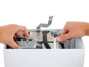
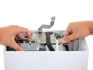
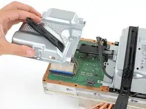
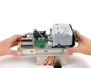
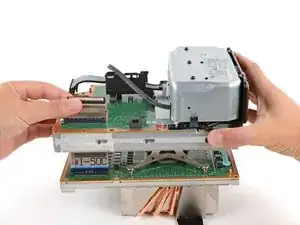
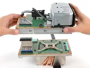
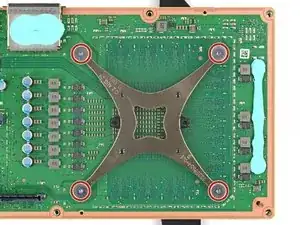
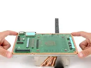
    • Grip the edges of the center chassis (not the power supply) and lift it off the motherboard and heatsink assembly, routing the interconnect cable through its cutout.

  39. QOB2kPTJTOJYwvaZ
    QOB2kPTJTOJYwvaZ
    kggARAyNEp6NyEsr
    • Use a T8 Torx driver to remove the 5.1 mm‑long screw securing the SSD.

    • With the SSD screw removed, the SSD will pop up at a shallow angle.

  40. bUDymMS1PwvooakA
    bUDymMS1PwvooakA
    SHyawFLCDk5HD3Z5
    • Grip the end of the SSD and pull it away from its M.2 board connector to remove it.

    • During reassembly, insert the SSD at a shallow angle into its board connector, and secure it back into its horizontal position with the SSD screw.

  41. 5iQZoVQ2DGDM3V1A
    5iQZoVQ2DGDM3V1A
    MJOrOERAhXYDeJo1
    eZNCxtJjGsGkdLBr
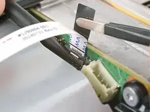
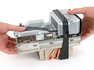
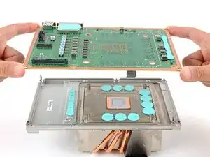
    • Pinch the locking tab on the interconnect cable on the motherboard and use the flat end of a spudger to disengage the clip.

    • Use your fingers to pull the connector straight up and out of its socket.

    • During reassembly, insert the #1—SOC side of interconnect cable connector into its socket so the locking tab is facing outward. Then, press down on the edges of the connector until it snaps into place.

  42. jA2qpQSAkVYaKT1G
    jA2qpQSAkVYaKT1G
    fOQ2DFy2bdel15Dm
    • Only loosen and tighten the APU tension bracket screws a few turns at a time in an "X" pattern. For example: top left → bottom right → top right → bottom left.

    • Use a T8 Torx driver to remove the four 12.4 mm‑long APU tension bracket screws.

  43. thhtWSWWcQJKVmHR
    thhtWSWWcQJKVmHR
    15iTVq4Cemnk3RWF
    • Don't move the APU bracket side to side, or you may damage the delicate surface‑mounted components underneath it. Only lift straight up.

    • Use your fingers to lift the APU bracket straight up and remove it.

    • During reassembly, set the bracket into place so the black pieces of plastic are facing the short edges of the motherboard—the piece of plastic with a circular hole (not oblong) should be closer to the SSD socket. Use this photo as a reference.

  44. 6Q4fiU5Hub14H2GJ
    6Q4fiU5Hub14H2GJ
    fPqQ2Ye4GR4yFUYZ
    GTk1nq4tIrbSCZVu
    • Depending on the condition of the thermal paste and putty, the board may be bonded to the heatsink assembly. If you can't easily remove the board, use a spudger to gently lift the edges of the board to separate it.

    • Use your fingers to lift the motherboard straight up and off the heatsink to remove it.

    • During reassembly, carefully place the board onto the heatsink with the APU facing down. Remember, there's exposed thermal paste on the bottom of the board, so use the alignment pegs to orient it correctly. If you have to reposition the board, it may smear the thermal paste.

  45. wpKLFwNEuuaCtnac
    wpKLFwNEuuaCtnac
    YLPMPwRmBE1kjEj1
    • Check the condition of the thermal putty—it'll be on the heatsink and/or the motherboard.

    • If any pieces are damaged or dried out, follow the next four steps to remove and replace them.

    • If you're only replacing the thermal paste, skip to this step.

  46. WCAntFuQLO36gUpN
    WCAntFuQLO36gUpN
    sCILuTMgMkAhVAZN
    jYqnp2FlC5ERJIiu
    • Use the flat end of a spudger to scrape off the damaged or deteriorated thermal pad.

    • Be careful around any small surface-mounted components that might be hidden under the thermal pad. Work slowly to avoid accidentally prying them off.

  47. ijvSwrb6ZFpjWKHb
    ijvSwrb6ZFpjWKHb
    qOsIxlqcu1ESNero
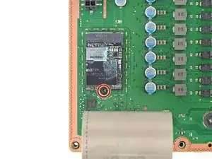
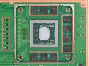
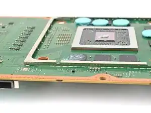
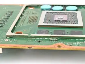
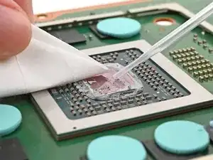
    • Use isopropyl alcohol (>90%) and a lint-free microfiber cloth to remove any thermal putty residue.

    • If you have to work near the small resistors, use cotton swabs instead.

  48. FtPRLiCCRuwnARnu
    FtPRLiCCRuwnARnu
    rN2VqFHRu6cldy4R
    • To prevent the thermal putty from sticking to your fingers, consider wearing nitrile gloves.

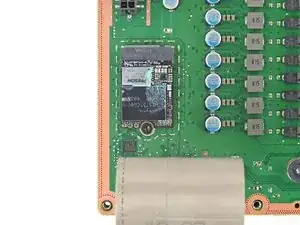
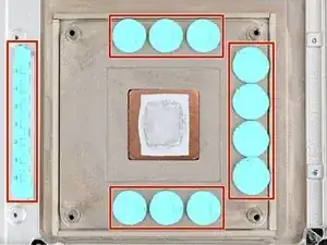
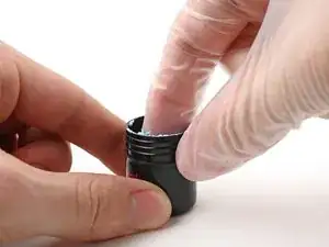
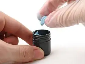
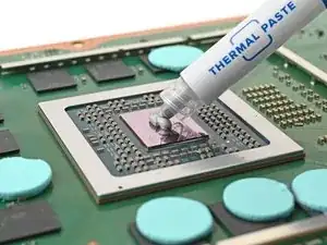
    • Grab a small piece of thermal putty. Refer to the size of the thermal pad you're replacing for how much you need.

  49. SVUgrbUJfI46MeKk
    SVUgrbUJfI46MeKk
    6CoQ1WZP4lL5J1fZ
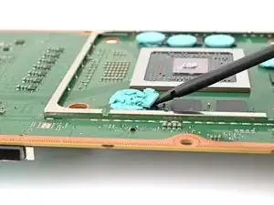
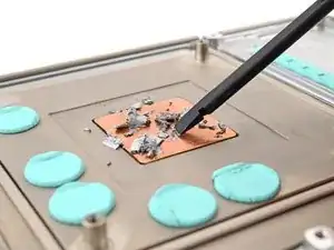
    • Roll the thermal putty into a ball.

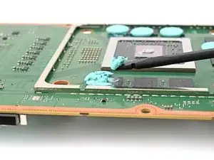
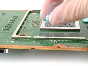
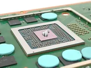
    • Place the thermal putty where the damaged thermal pad was, making sure it's centered over the component—in this case a memory chip.

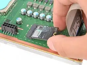
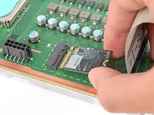
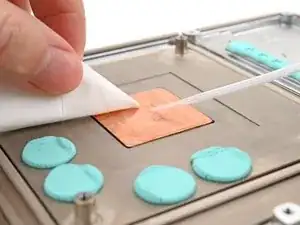
    • Optionally, you can use the flat end of a spudger (or an included applicator) to spread the thermal putty over the surface of the component.

    • When you reattach the heat sink, you'll compress the thermal putty and it'll spread the ball out.

  50. I13roaCQAyTsMSRD
    I13roaCQAyTsMSRD
    2dTnxkTQfoj164el
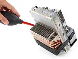
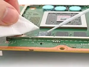
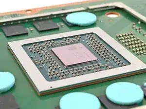
    • Apply a few drops of isopropyl alcohol (>90%) to the processor and use a coffee filter or a lint-free cloth to wipe away any residue.

    • If you have to work near the small resistors, use cotton swabs instead.

  51. niVQvEKLHSZPyhtU
    niVQvEKLHSZPyhtU
    43AQNEmMsFQN2FhN
    • Repeat the previous step for the thermal paste on the heat sink.

    • You can use a spudger to scrape off the thermal paste on the heat sink if it's too dried out.

  52. tHG1D2FxhlkNY2Fs
    tHG1D2FxhlkNY2Fs
    XENsLwLSITUy2Z6Q
    • Apply a small bead of thermal paste to the center of the APU.

    • Follow this guide in reverse order starting with this step to reattach the heat sink. Placing the heat sink back on the processor will evenly spread the thermal paste (and thermal putty if applicable) and bond both parts together.

Conclusion

To reassemble your device, follow these instructions in reverse order.

Take your e-waste to an R2 or e-Stewards certified recycler.

Repair didn’t go as planned? Try some basic troubleshooting, or ask our Answers community for help.

Spencer Day

Member since: 14/09/22

95592 Reputation

0 comments