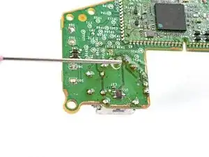
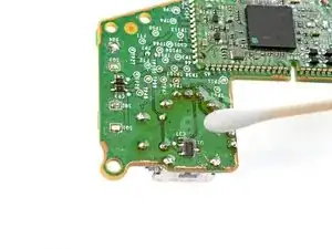
Introduction

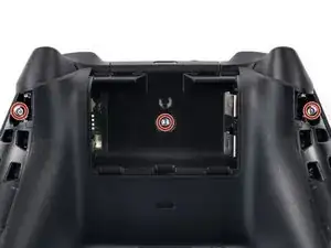
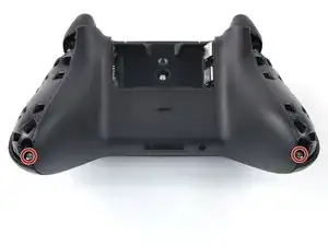
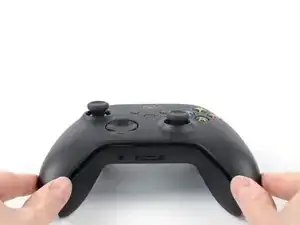
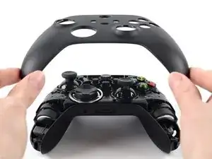
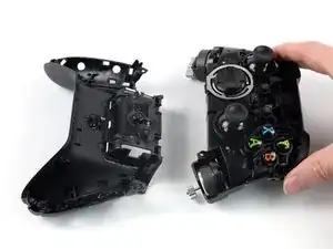
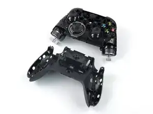
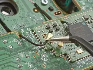
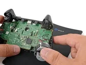
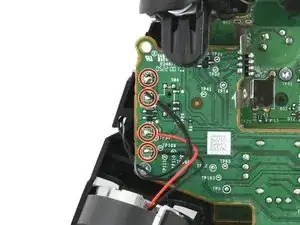
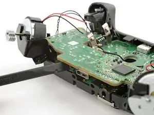
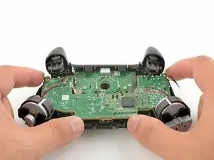
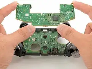
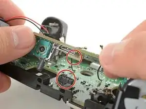
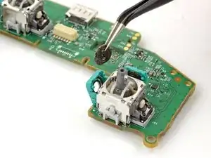
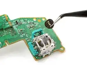
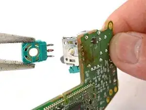
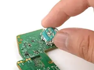
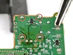
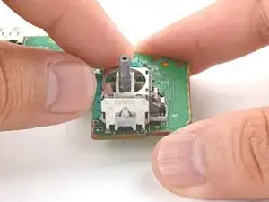
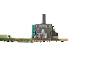
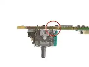
Follow this guide to replace a broken or drifting joystick (aka thumbstick or analog stick) for the Xbox Series X/S wireless controller. If you experience persistent stick drift, you can't fix it by cleaning your controller—it's likely a worn out joystick module.

This repair requires intermediate soldering skills. While no single step is super difficult, removing the existing joystick module is by far the hardest part.

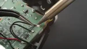
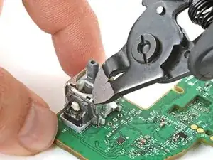
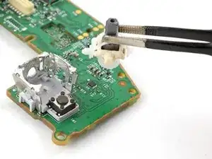
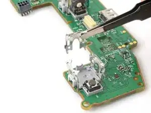
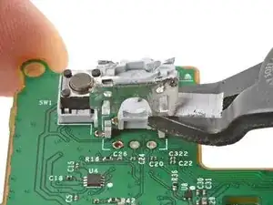
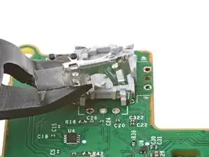
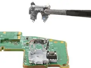
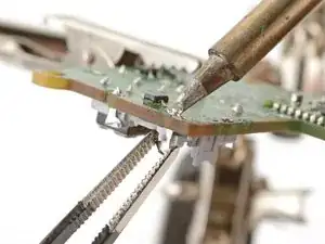
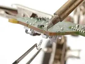
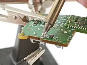
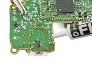
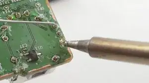
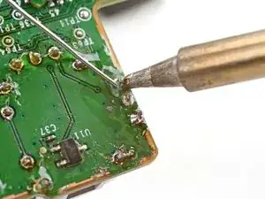
If you have a hot air station, you can use it to desolder all the contacts simultaneously to extract the joystick. This guide, however, shows how to cut apart the joystick module so that you can desolder the pieces individually with a soldering iron.

Replace the drifting joystick with a TMR joystick module to fix stick wear and drift permanently.

  1. fGWBOKPHpp5HSnQr
    fGWBOKPHpp5HSnQr
    n4xIYV6MgTJFeT5L
    uG16NxBaI1wQ55wj
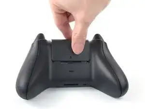
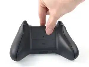
    • Use your fingers to slide up and remove the battery cover.

  2. 41oB3Y5hrGhLowJA
    41oB3Y5hrGhLowJA
    SVRVCSruSUYZgHHu
    ytLV5hMcGPosxwAd
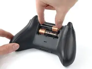
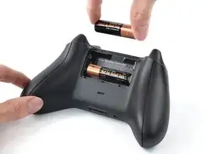
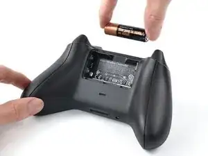
    • Remove the batteries.

    • When re-inserting the batteries, make sure to position them correctly, with their positive (+) and negative (–) ends matching up with the markings on the controller’s battery contacts. If your batteries are starting to corrode, replace them with new batteries.

  3. SKZEdX3QSobavyu3
    SKZEdX3QSobavyu3
    binvfjuvoi62cBwh
    UV2gdW4lFjg22uLB
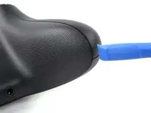
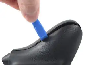
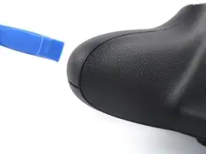
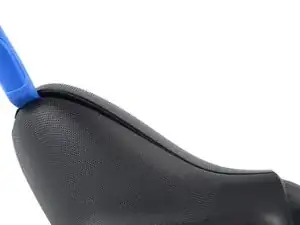
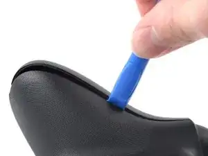
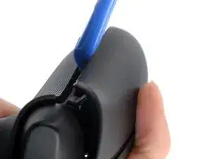
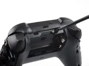
    • Insert an opening tool between the left handle cover and the bottom inner edge of the back housing.

    Before doing this step, it is recommended to clean the edges of the cover

    Violynos -

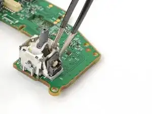
    Thanks for adding this tip!

    Manuel Haeussermann -

  4. WPfNqN1dPbKCXZIs
    WPfNqN1dPbKCXZIs
    XlvLyUmboPT4JgmW
    v6CYYaJYwHyQsiSP
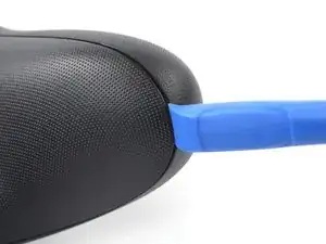
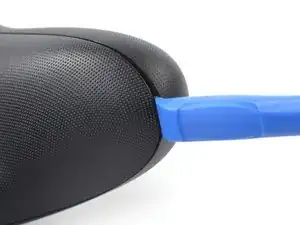
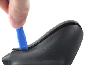
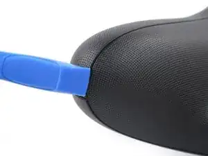
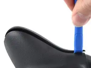
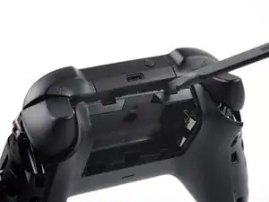
    • Strong plastic clips secure the handle cover. Significant force is required to release them.

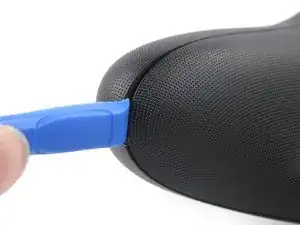
    • Slide the opening tool along the inner edge of the left handle cover and pry intermittently to release the plastic clips.

  5. PYLnCUqAkTPfkfMZ
    PYLnCUqAkTPfkfMZ
    ENNxbJI6gGpP6Ij4
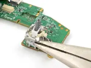
    S5LCNcRyNBUtIKsR
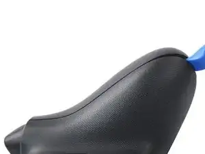
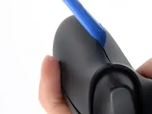
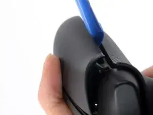
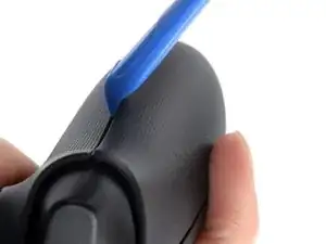
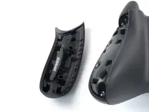
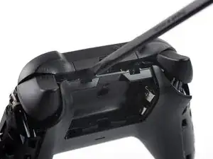
    • The plastic clips on the outer edge make it difficult to slide along it and release the clips. Therefore, prying up on the inner edge is the easier option.

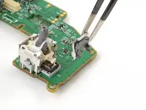
    • Pry up the middle inner edge of the handle cover with the opening tool to release the remaining clips.

    • Place a finger on top of the handle cover to prevent it from being forcefully ejected.

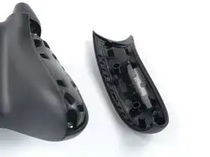
    • Remove the left handle cover.

    • To reinstall the left handle cover, position it on the back housing and press down firmly along the edges to engage all of the clips.

  6. nc2jnwSRKrtckCcy
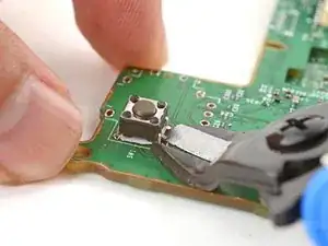
    nc2jnwSRKrtckCcy
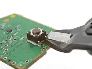
    2RvcVdnxMAucHZDK
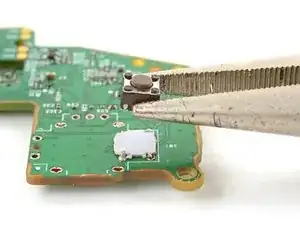
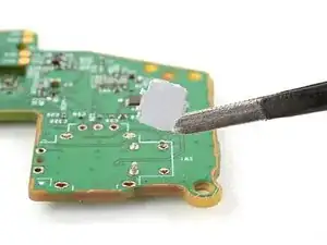
    hNtWlQH2fwXvYkjj
    • Insert an opening tool between the right handle cover and the bottom inner edge of the back housing.

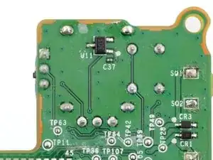
  7. nPeROMGOeOcOLgxm
    nPeROMGOeOcOLgxm
    dJdKQkOnjlsnR4OK
    1oIFaTi6p5fYwJJ4
    • Strong plastic clips secure the handle cover. Significant force is required to release them.

    • Slide the opening tool along the inner edge of the right handle cover and pry intermittently to release the plastic clips.

  8. hRluiJFD65Xvf1oO
    hRluiJFD65Xvf1oO
    jLU4F1WGBaGKVHku
    xJC3GcDk2glqVaud
    • The plastic clips on the outer edge make it difficult to slide along it and release the clips. Therefore, prying up on the inner edge is the easier option.

    • Pry up the middle inner edge of the handle cover with the opening tool to release the remaining clips.

    • Place a finger on top of the handle cover to prevent it from being forcefully ejected.

    • Remove the right handle cover.

    • To reinstall the right handle cover, position it on the back housing and press down firmly along the edges to engage all of the clips.

  9. BQcFXKHL51fKEWJD
    BQcFXKHL51fKEWJD
    HDdlQYkVHHTCT1KW
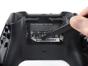
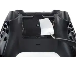
    • The sticker in the battery compartment covers a housing screw. Peel it back or pierce through it with a screwdriver.

    • Use a pair of tweezers or your fingers to peel back the sticker to reveal the screw.

    • You only need to peel this sticker to where you can access the hidden screw. You don't need to pull it completely off.

  10. e1LH5a14nJoEjC4q
    e1LH5a14nJoEjC4q
    FCBvqqV1hmh4XXvA
    • Use a Torx T8 Security driver to remove the five 9.3 mm-long screws securing the top housing, three near the top and two at the bottom.

    I found that for me a T8 H screw (the one with a hole in the middle) works better.

    Violynos -

    Hi Violynos, thanks for your comment! The designation Torx T8 security screw is equivalent to Torx T8H.

    Manuel Haeussermann -

  11. M2PiWeABAXUiy1Q2
    M2PiWeABAXUiy1Q2
    C5vyDdF1Mv3prJew
    WILZkeALQ4PDMQOl
    • Lift the top housing straight up to remove it.

  12. ITwt4DI3gTgQepMF
    ITwt4DI3gTgQepMF
    FZFOIrs5HMIQG2yX
    CL5xFVp5dwu4uInJ
    • Insert the flat end of a spudger into the rectangular gap between the midframe assembly and back housing, nearest the left bumper.

    • Twist the spudger to partially release the midframe assembly.

    • Repeat this prying procedure on the gap near the right bumper to completely release the midframe assembly.

  13. NONRDcRpvJVM3C2I
    NONRDcRpvJVM3C2I
    PrIWAkBnhCkCYlGF
    TunqTO3Gc5jPwokO
  14. kPsOCUAjhtKSew4K
    kPsOCUAjhtKSew4K
    LmHaYab1rKZMAhQb
    gWbr5BUhIFouDC6J
    • Slide one arm of a pair of tweezers under the antenna coaxial cable connector, as close to the metal head as possible.

    • Lift the connector straight up to disconnect it.

    • Be sure to lift the coaxial connector straight up off of the socket to avoid bending the connector.

    • Repeat the procedure for the second antenna cable.

    • During reassembly, align the connector over the socket and use your finger to press it into place. A tool like a spudger can slide off and damage the surface-mounted components around the connector.

  15. fgYthGh5uwG1OFY2
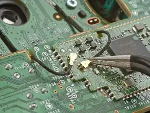
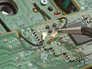
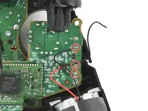
  16. Use your soldering iron to heat up one of the motor wire solder pads.
    • Use your soldering iron to heat up one of the motor wire solder pads.

    • Once the solder is melted, use tweezers to lift the wire away from the pad.

  17. PwbOfYP6OAU25Lxq
    PwbOfYP6OAU25Lxq
    wPA25LAtlusQxaZx
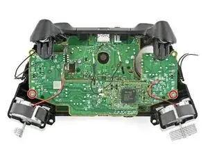
    • Desolder the seven remaining wires connecting the four motors to the circuit board.

    • When you resolder these wires during reassembly, make sure to solder the red motor wires to the pads marked SQ3 and SQ7. This ensures that the large rumble motors spin in the correct direction.

  18. bvEvRS1Ha6ujPffK
    • Use a Torx T5 driver to remove the two 7 mm‑long screws securing the daughterboard.

    These are T6 Screws, not T5,

    Vincent -

  19. nkfPnjZuGGfZw2Bl
    nkfPnjZuGGfZw2Bl
    5WODy6dbQrdEsCFv
    SZWEnt6qTKMRGc6H
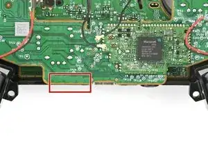
    • The daughterboard is still connected to the main board by a socket.

    • Insert the flat end of a spudger between the daughterboard and the bottom edge of the frame at the location marked on the image.

    • Twist the spudger to push up the daughterboard and disconnect the socket.

  20. 6Yydv1VZ4HLDMEMY
    6Yydv1VZ4HLDMEMY
    H3OPLqxvIGQqDndq
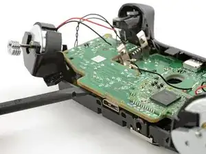
    • Lift and remove the daughterboard.

  21. kJ3RvaQJUW6RmsiP
    kJ3RvaQJUW6RmsiP
    sul4IlbTOTNEWwqU
    arw5DNrCG4BoJLZj
    • During reassembly:

    • Line up the daughterboard socket to the main board socket.

    • Check that the headphone jack isn't out of position.

    • Check that the antenna cables aren't trapped between the two boards.

    • Use your fingers to gently squeeze the boards together to reconnect the socket.

  22. 2PjI1QsutQtKBFMJ
    2PjI1QsutQtKBFMJ
    14iMG2D1AwO2Grg1
    XCHTjTmoaTSUDNWm
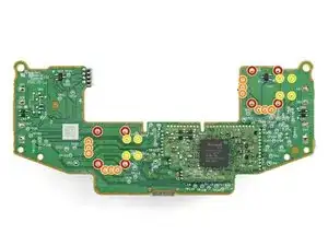
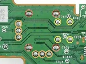
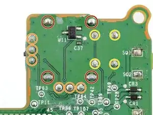
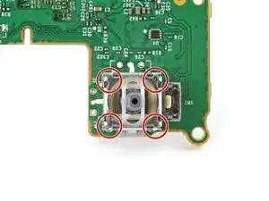
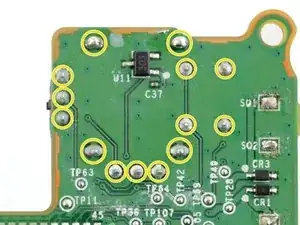
    • Each joystick module is secured with 14 solder joints:

    • Four frame anchor joints

    • Six joints connecting the two potentiometers

    • Four joystick push-button joints

    • The remaining steps will show how to remove and replace the left joystick (with the controller facing you). If you're replacing the right joystick, you can follow the same procedure.

  23. hYe4o6IWu2RjYAgO
    hYe4o6IWu2RjYAgO
    QvDUBNLbRvKRnWLi
    TcOrSKRV1CDtPhqS
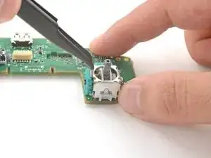
    • Insert the tips of a pair of angled tweezers between the top edge of a potentiometer and the joystick frame.

    • Pivot the tweezers to bend the top edge of the potentiometer away from the joystick frame.

    • Repeat the procedure with the second potentiometer.

  24. wxbewykagK4GWvLM
    wxbewykagK4GWvLM
    huEhTaV61FTFUj5Y
    1RiAQNUSohFmaFJ1
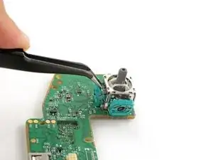
    • Use tweezers to remove the round wiper mechanism out of both potentiometers.

  25. qgwoIch3uo3BonK6
  26. NBtsQCnLoJRXQac6
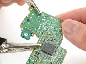
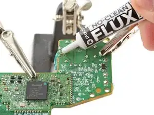
    • Apply flux to the three solder joints securing one of the potentiometers.

    • Flux improves the flow of molten solder, which makes it easier to work on. If you're having trouble with goopy or sticky solder, apply more flux to fix the behavior.

  27. For full instructions on how to desolder through-hole solder joints, <a href="../../Guide/How%2BTo%2BSolder%2Band%2BDesolder%2BConnections/750" target="_blank">click here</a>.
    • For full instructions on how to desolder through-hole solder joints, click here.

    • Set your soldering iron to 375 °C (707 °F) and press the tip against a joint to heat it.

    • Don't heat the joint longer than 15 seconds at a time, or you risk damaging the solder pad.

    • If you're having trouble melting the solder joint, apply some leaded solder onto your soldering iron tip and try again. The leaded solder helps with heat transfer while lowering the melting temperature of the existing lead-free solder joint.

    • Once the joint's molten, use a desoldering pump to suck away the solder.

    • Repeat the heating and sucking procedure a few times on the same joint to remove as much solder as possible.

    • Don't heat the joint continuously for longer than 15 seconds at a time to avoid damaging the pad.

  28. qOSjKGYXqjFu24Ih
    • Repeat the procedure to desolder the remaining two joints securing the potentiometer.

  29. 4MIcUQbcDWShZKAm
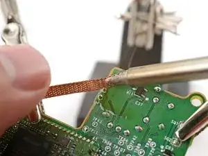
    • This step shows how to remove solder residue with a solder wick. If the potentiometer feels loose, skip this step.

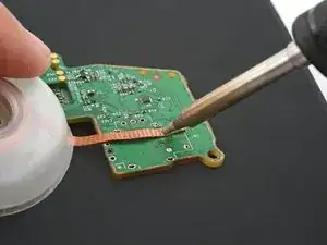
    • Apply flux to the solder joint.

    • Lay a piece of clean solder wick over the solder joint.

    • Press the tip of your soldering iron over the wick so that the residue melts and transfers onto the wick.

    • Repeat the process with the remaining two solder joints.

  30. 5dWWTfYobbInhqSc
    5dWWTfYobbInhqSc
    onJa4yWusjUhSKbW
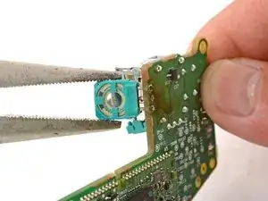
    • User tweezers or pliers to gently pull the potentiometer away from the board.

    • Don't pull excessively, or you'll rip out a solder pad. If the potentiometer feels stuck, follow the previous three steps to try to remove the solder residue holding the potentiometer in place.

    • You can also try heating each joint as you wiggle the potentiometer out of the board. This is best accomplished with extra helping hands from a friend.

  31. wb61AOKBXftVKfUf
    • Repeat the desoldering procedure to desolder the second potentiometer.

  32. LEtZB2cTjNXsCAMG
    LEtZB2cTjNXsCAMG
    YAeAkYNw1JkyFDFd
    iFQR663V1OBB56DO
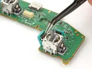
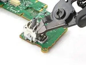
    • Use flush cutters to cut the top corners of the joystick frame.

    • Be very careful not to cut yourself on the sharp edges. Bend any sharp edges down with pliers.

  33. HiWYYjaQZsqdLpZC
    HiWYYjaQZsqdLpZC
    JeRte2T6Q2jm11JN
    • Remove any loose frame pieces from the joystick module.

  34. BPGWoJhGfSgbwQFI
    BPGWoJhGfSgbwQFI
    lu6FAJIIBSAOYi6a
    • Use pliers to bend the remaining frame sides outward.

  35. XBPaGAr2B6Svd6FZ
    XBPaGAr2B6Svd6FZ
    ev14P3yGZXVISLxj
    • Remove the plastic joystick components from the center of the frame.

    • Remove any loose frame pieces.

  36. teX1i1xvamgUJcdb
    teX1i1xvamgUJcdb
    RXk1uTGbJYZGuqy4
    2eGhqaH6eM6xihnS
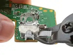
    • Use flush cutters to cut both legs for one of the frame walls.

    • Remove the loose frame wall.

  37. dAxUp1Yt1N2qCwkZ
    dAxUp1Yt1N2qCwkZ
    sBAQCTHFOYYwhDDc
    XHLQsygg1VsyVJxC
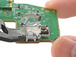
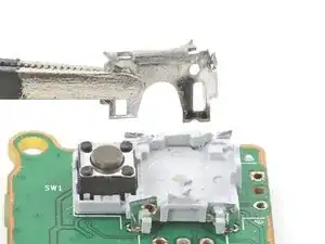
    • Repeat the procedure to cut and remove the last frame wall.

  38. qSfsZcT4EPFhSHqG
    qSfsZcT4EPFhSHqG
    RRXwwPKyxrRNjGbH
    YPFZpaqH51qffQ11
    • Secure the circuit board so that the solder joints face upward.

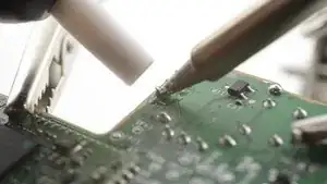
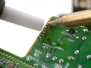
    • Use your soldering iron to heat a solder joint securing one of the frame anchors.

    • Once the solder is melted, use tweezers to grab and pull the frame anchor out of its through-hole.

    • If you're having trouble melting the solder joint, apply some leaded solder onto your soldering iron tip and try again.

  39. bOCgYyBtZnBKTgI1
    • Repeat the procedure to remove the remaining three frame anchors.

  40. 5YPjORIcqFrktDtA
    5YPjORIcqFrktDtA
    h1xRAhmGPWRwyQfx
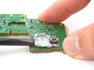
    • Slide the flat end of a spudger under the joystick module's plastic base.

    • Pry up slowly to bend and break the base away from the circuit board.

    • Remove the plastic base.

  41. u1HdKQidgIEnZXrL
    u1HdKQidgIEnZXrL
    KTvZe5MNLj1VSBEr
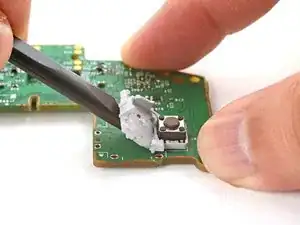
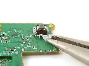
    • Use flush cutters and pliers to break and remove the plastic base remnants from the push-button.

  42. DZRghRXY3OQFjRHF
    DZRghRXY3OQFjRHF
    tXwNrWaWhxdTunVq
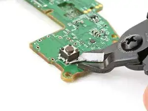
    • Use flush cutters to cut the four push-button pins along the bottom edge of the button, securing it to the circuit board.

  43. 1gjBUGpI2aCWtnuZ
    1gjBUGpI2aCWtnuZ
    H5KmKHMqowETUMTD
    • Remove the push-button.

    • Remove any plastic base remnants.

  44. dpGj4XU2RlFBVHTN
    dpGj4XU2RlFBVHTN
    aXxqGkJ53JF1NJBr
    • Secure the circuit board so that the solder joints face upward.

    • Use your soldering iron to heat a solder joint securing one of the push-button pins.

    • Once the solder is melted, use tweezers to grab and pull the pin out of its through-hole.

    • Repeat the procedure to remove the remaining three push-button pins.

  45. m2ZT4fPguGXXNa4t
    m2ZT4fPguGXXNa4t
    VZnw3WeM6IuNaqYI
    QWT1GSOmsdRgJ6FL
    • Use your soldering iron to heat up a through-hole on the circuit board.

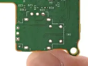
    • Use a desoldering pump to suck up any solder residue from the through-hole.

    • To clear out through-holes, heat it from one side and use the desoldering pump to suck through the hole from the other side.

    • You can also use solder wick instead to remove the residual solder.

    • Repeat this for all through-holes and both sides of the circuit board.

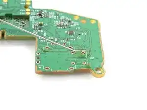
  46. cDrwNoiiUCTlVYsH
    • Visually inspect each through-hole and make sure they're not blocked by solder residue. If some holes look blocked, repeat the previous step to clear the blockage.

  47. rk3vJaGpldFhNXBD
    rk3vJaGpldFhNXBD
    FbiMIsUUQ5VFvieI
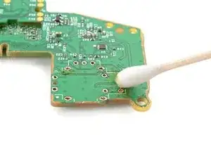
    • Apply a few drops of high concentration (>90%) isopropyl alcohol to the top side of the circuit board, where the new joystick module will sit.

    • Use a cotton swab or a soft brush and cloth to wipe away the flux residue.

  48. j4NRIdDbMbpiUXNq
    j4NRIdDbMbpiUXNq
    PNpWrVbAbRG6OPwS
    • Place the replacement joystick module onto the circuit board.

    • Gently press the joystick onto the board so that the joystick sits flush with the board surface.

  49. o1sPQNYHCUQR6kvR
    • Flip the circuit board over and secure it so that you can solder the joystick module pins.

    • Apply flux to the first few solder pads that you're going to solder.

  50. Solder one of the pins to the circuit board.
    • Solder one of the pins to the circuit board.

    • It may be helpful to solder one of the frame anchors first, so that the joystick will be more stable to work on.

  51. Tq5hJLJlKYlbJDsk
    Tq5hJLJlKYlbJDsk
    cq6g1XXxBR1JPiAZ
    DjqGTUF1HqEhFvOP
    • Make sure the joystick module hasn't moved away from the circuit board during the soldering process. Reheat the soldered pin and reposition the module as needed.

    • Solder the remaining pins (14 total) to the circuit board. Apply flux as you solder to help create good bonds.

  52. jRFGYkWe2LxJwhqd
    • Visually inspect your work:

    • Make sure each solder joint looks well-formed.

    • Make sure there are no unintentional solder shorts.

  53. JHUZjAEYYFJxM6H5
    JHUZjAEYYFJxM6H5
    wMMXJAwOnS6dcppM
    • Apply a few drops of high concentration (>90%) isopropyl alcohol to the circuit board, wherever you can see flux residue.

    • Use a cotton swab or a soft brush and cloth to wipe away the flux residue.

Conclusion

Congratulations! You've replaced your controller's joystick and, in the process, leveled up your soldering skills.

To reassemble your controller, go to this step and follow the instructions in reverse order.

You'll need to run the thumbstick recalibration tool to calibrate your new joystick:

  • On an Xbox, press the Xbox button on the controller, then navigate to Settings Devices & connections Controllers & headsets.
  • On a PC, download the Xbox Accessories app and look for the recalibration option.

Take your e-waste to an R2 or e-Stewards certified recycler.

Repair didn’t go as planned? Try some basic troubleshooting, or ask our Answers community for help.

Arthur Shi

Member since: 03/01/18

282916 Reputation

6 comments

Happy to report this worked perfectly fine for me, even though my soldering skills are quite bad. Un-Soldering the old parts was quite a tidious task, but going slowly and steady finally made it work. Overall i would say it took me around 4 hours to complete (3,5h of that were for the soldering part ^^).
After reconfiguring the thumbsticks within the xbox internal settings app, everything works perfectly.

Kokaninchen -

OMG, de-soldering the old joysticks was hard, mostly because of big thermal mass of the GND pins. What helped me, was to use a big soldering tip (chisel tip) to remove old pins one by one (when, as per the instruction I pretty much cut old parts into pieces which made removing individual pins separately possible), and then I used fine tip putting it into each THT hole and sucked solder from the other side. Great guide!

Łukasz Iwaszkiewicz -

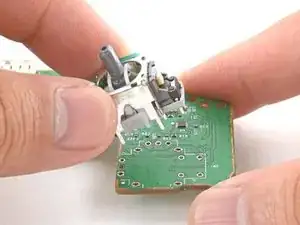
I just completed it and the guide was excellent. I used a hot air station i got for Christmas and it made it so god damm easier BUT make sure you add some kapton tape on the bottom of your new sticks so you dont melt the plastic, i did it on one of the sticks and now its kinda weird.

Also be very careful with the antennas, i think i bumped one of the connectors with my iron or something and now it wired only, but thats ok since its only used at my desk or connected to my switch thru a cable

Overall this is a very good guide for a very hard job, but if i had to reccomend some changes i would add the tip suggestions from @lukasziwas53885 since those were great tips from him
Verhulstak -

I think I messed up 2 solder pads on the right joystick. I have cleaned it a lot added flux but the solder just sticks to the iron and not the pads or pin. Everything else was fine and the left joystick works great. Any help is appreciated.

Shaun Evans -

The only thing I can think of is to use different flux maybe? For very stubborn things (this fix qualifies) i use AMTECH NC-559. I think Louis Rossmann recommended it on one of his videos.

Łukasz Iwaszkiewicz -

Buenas tardes, he reemplazado ambos joysticks pero quedo tirando para la izquierda solo y no se deja calibrar, que puede ser si he reemplazado por otro y me presenta el mismo problema. Ayuda !!!!

Raoulo Hernandez -