Introduction

Use this guide to apply liquid metal in your PlayStation 5 Slim. You can also use this guide to re-spread existing liquid metal.

Your PS5 Slim has an Accelerated Processing Unit (APU), which uses liquid metal TIM (thermal interface material) instead of traditional thermal paste to transfer heat. Over time, the liquid metal can oxidize or become unevenly spread on the APU and heatsink, especially if the PS5 Slim stood upright for long periods of time. If the liquid metal has oxidized, it'll look dried-out or cracked and will need to be cleaned and replaced. If it's just unevenly covered, you can re-spread it evenly across the surfaces of the APU and heatsink.

Your liquid metal might need to be replaced if your PS5 Slim is overheating, throttling, or having overall poor performance. These signs could also mean a faulty or dirty fan. To remove your fan for cleaning, follow this guide.

  1. VIoiTVZ1Ev5TaOCc
    VIoiTVZ1Ev5TaOCc
    GFXYaIEhkDaHBRKO
    1mlnNILor6mKjdWi
    • Before starting your repair:

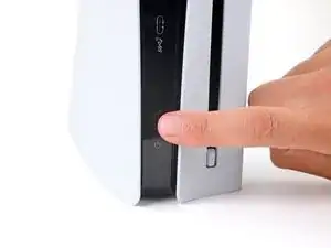
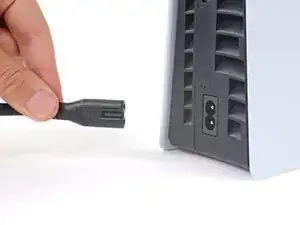
    • Shut down your console and unplug all cables and accessories.

    • Remove any stands supporting your device and lay it down.

  2. uURDSJZtjgXZlI3C
    uURDSJZtjgXZlI3C
    1RJYOupWshUYNnRB
    BONnefLqPt24HRRX
    • Each console cover is secured with hooks along the rear edge and clips along the front edge.

    • To remove a cover, firmly pull up the front edge to release the clips.

    • You'll hear distinct "pops" as the clips release.

    • Remove the cover.

  3. EOSDiJSlTg1ckboY
    EOSDiJSlTg1ckboY
    b5fnmybSyI1PBiqd
    mhTx5IOIXiibFO26
    • Use the same process to remove the three remaining covers.

    • To reinstall a cover, place the hooks into their cutouts along the rear edge and firmly press the front edge of the cover into place to re‑engage the clips.

  4. dlNXBLHjW244VAvQ
    dlNXBLHjW244VAvQ
    lvPr2RUIxiKwZUq2
    f6xOnXIpyHPU5lhY
    • If your PlayStation doesn't have a disc drive, skip this step.

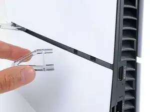
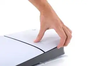
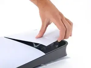
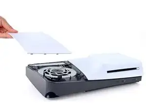
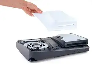
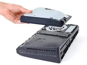
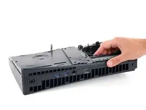
    • Use the cutout on the bottom right corner of the disc drive to lift its right edge and disconnect it.

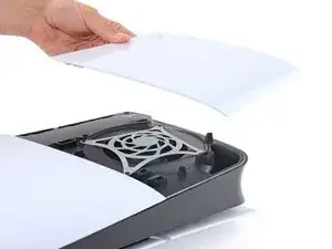
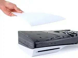
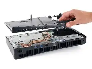
    • Remove the disc drive.

    • During reassembly, place the hooks on the left edge of the drive into their cutouts and firmly press the drive into place so the connector on the bottom right corner goes into its socket.

  5. jSvmTWU4XgQLNXOh
    jSvmTWU4XgQLNXOh
    An2u23cXafS2TR4K
    • Throughout this repair, keep track of each screw and make sure it goes back exactly where it came from.

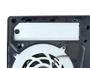
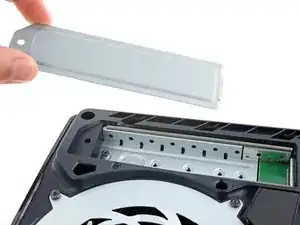
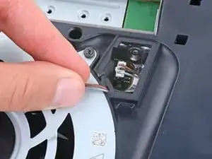
    • Use a Phillips screwdriver to remove the 17.1 mm‑long screw securing the expansion slot cover.

  6. 2kSqR3tLphnInaZW
    2kSqR3tLphnInaZW
    MejFxTYVGQPKZBZU
    k4ZeZTS6ra6bPZuT
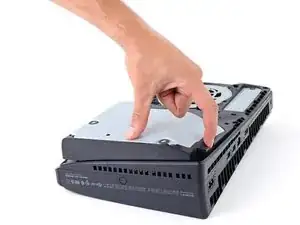
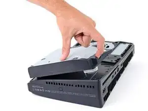
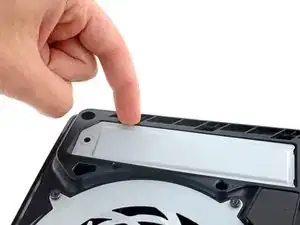
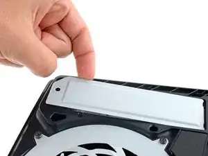
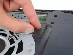
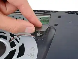
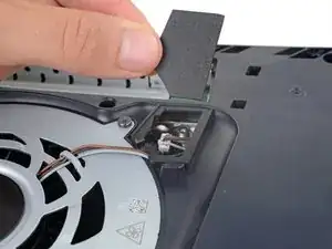
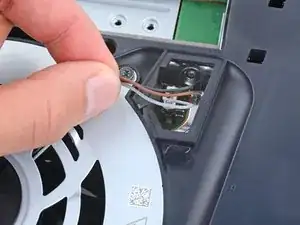
    • Use your fingers to lift the expansion slot cover near the notch by the screw hole and remove it.

  7. Haf4mDbsJlSLAnEJ
    Haf4mDbsJlSLAnEJ
    JxIpwPODeUS6vMCO
    H4X1RGawjrOXxgxV
    • Use your fingers to remove the plastic cover hiding the fan cables connector.

    • The cover is secured with light adhesive.

    • During reassembly, press the piece of plastic back into place to secure it with the leftover adhesive. If it isn't sticking, use strips of double-sided tape to secure it.

  8. nq1rhobOjJPUN2fw
    nq1rhobOjJPUN2fw
    ZhcuKNQLRioMLLTX
    • Gently pull the fan cables out from under their plastic clip on the frame.

  9. 4UtHMkosrW32eE2P
    4UtHMkosrW32eE2P
    ZTPMZoohZSjNRxR1
    uKcstxPpUvImCrDg
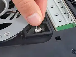
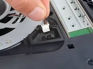
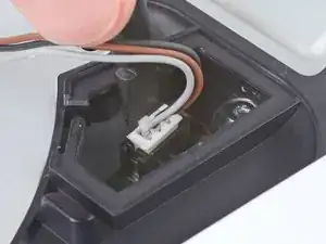
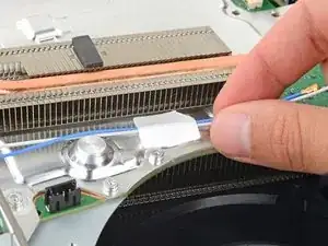
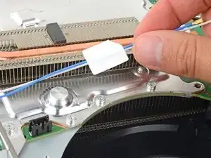
    • Firmly grip the fan cables white connector head and pull it straight up and out of its socket.

    • If you're having trouble, grip the cables just above the connector head, and gently pull.

    • During reassembly, align the connector over its socket and push down on the edges with the flat end of a spudger until it slides fully into its socket.

  10. ZpkgRuvtcn1EqCyP
    ZpkgRuvtcn1EqCyP
    SMTt6aJ2WGKsWGlC
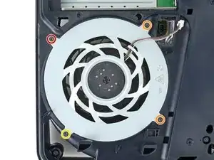
    • Use a T8 Torx Security screwdriver to remove the four screws securing the fan:

    • One 31.2 mm‑long screw

    • Two 21.3 mm‑long screws

    • One 11.6 mm‑long screw

  11. b5obnDWhkEuIQ26R
    b5obnDWhkEuIQ26R
    5yDx2x1QL3GSS6gi
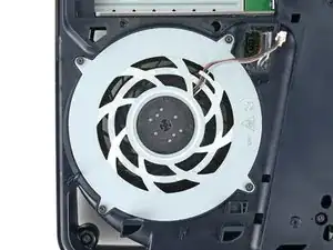
    • Use your fingers to grab the fan by its vents, and lift it straight up to remove it.

    • During reassembly:

    • This is a good point to clean the fan. Use a clean cloth and some compressed air to remove any dust or dirt.

    • Insert the fan so its cables are near their connector.

  12. hRFia5Dfr2jPlst4
    hRFia5Dfr2jPlst4
    qPD4ps4Wn6hHmjld
    LvJOXXtcIULdToRY
  13. 5S4CoqkDv4Qr1CEw
    5S4CoqkDv4Qr1CEw
    vSnxgNZflwRCYUFJ
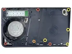
    • Use a T8 Torx Security screwdriver to remove the nine screws securing the main board cover:

    • Four 18.9 mm‑long screws

    • One 21.3 mm‑long screw

    • Four 31.2 mm‑long screws

  14. 66BRjLfBZgMySYOP
    66BRjLfBZgMySYOP
    qJoCpqWvsdjnEONo
    • Lift the main board cover straight up and remove it.

  15. ggEhIlHFWXYUTjE5
    ggEhIlHFWXYUTjE5
    mWMDIgvy1v2egqKH
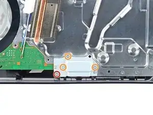
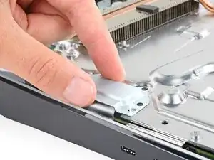
    • Use a T8 Torx Security screwdriver to remove the four screws securing the interconnect cable cover:

    • One 28.7 mm‑long screw

    • Three 7.5 mm‑long screws

  16. ER6YIHliEdTna4FN
    ER6YIHliEdTna4FN
    4dklDl2GYilgq6Af
    • Remove the interconnect cable cover.

  17. ddlt6uQFqAvdex2h
    ddlt6uQFqAvdex2h
    FHhXWFlD6hb2wSxt
    yBdmLUfHxCjrg1UR
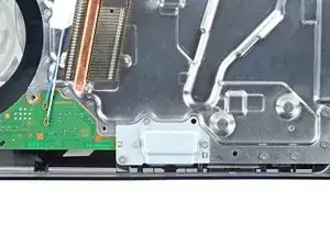
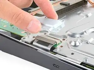
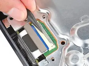
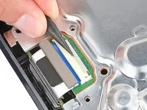
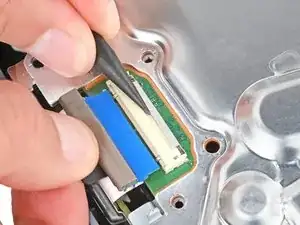
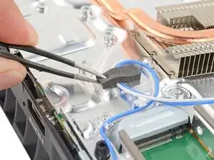
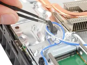
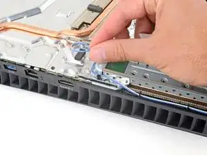
    • Use the point of a spudger to push the interconnect cable's metal latch down and away from the connector to unlock it.

    • Keep the latch in its unlocked position and carefully pull the interconnect cable straight out of its socket.

    • During reassembly, push the latch into its unlocked position and insert the cable into its socket. Then, push the latch back in place to lock the cable.

  18. 4qNF2ybQMlvurEw2
    4qNF2ybQMlvurEw2
    ak2EmFkdAmA1Nl4W
    VZsevWoojMqeGgTT
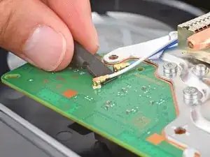
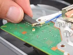
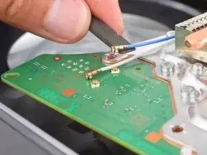
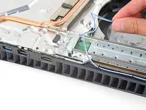
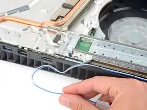
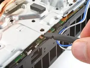
    • Insert the flat end of a spudger under the metal neck of one of the antenna cable's coaxial connectors and lift straight up to disconnect it.

    • Repeat the process to disconnect the other antenna cable.

    • To reconnect a cable, hold the metal connector head over its socket and press down with the flat end of a spudger until the connector snaps into place. Don't try to force the connector into place. If you're having trouble, reposition the connector and try again.

  19. upXWsWZUJ4SPSlaD
    upXWsWZUJ4SPSlaD
    xSktSZnet4ScSlto
    • A piece of tape and a block of foam secure the antenna cables to the heatsink shield.

    • Gently lift both antenna cables to separate the tape from the heatsink shield.

  20. Qw1RP6WoIRS4FhDX
    Qw1RP6WoIRS4FhDX
    WEtMxEqWfJOumTYR
    • Light adhesive secures the foam block to the heatsink shield.

    • Use tweezers to gently peel up the foam block.

    • If you're having trouble, heat an iOpener and apply it to the foam for one minute to soften the adhesive. If you don't have an iOpener, you can use a hair dryer instead.

  21. 2ZoSfoqOqX4vg2LT
    2ZoSfoqOqX4vg2LT
    cCl12m2MAdNrfReL
    wHOl11NTxZrLLhu1
    • Move the antenna cables over the side of your PlayStation so they're out of the way.

    • During reassembly, use this photo as a reference to put the antenna cables back in their original position.

  22. Ax1Jo4UDYJIcAZyu
    Ax1Jo4UDYJIcAZyu
    5eppJxB12eYoPqhe
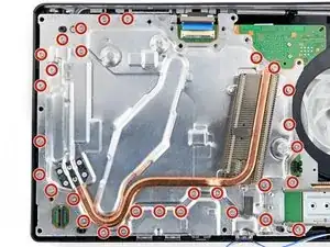
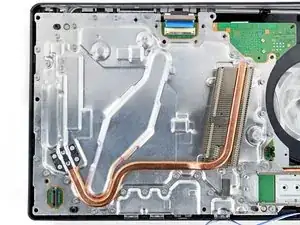
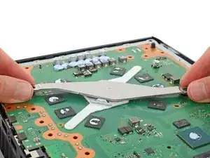
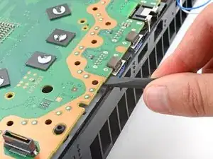
    • Use a T8 Torx Security screwdriver to remove the thirty 7.5 mm‑long screws securing the top shield plate.

  23. SSTQEixgWnbJInfw
    SSTQEixgWnbJInfw
    lEfPXA1RtOPRHJ1L
    uUQfL3SEBunYQbDu
    • Thermal pads bond the top shield plate to the main board. Depending on the age of your device and conditions of the pads, it may take significant force to separate the plate.

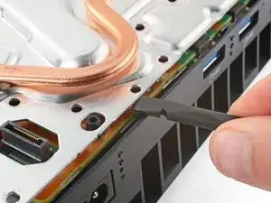
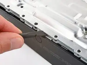
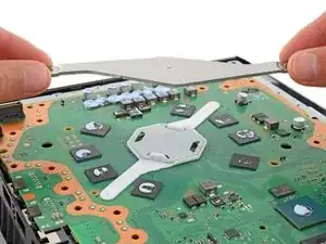
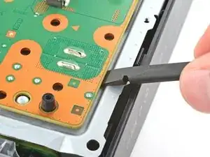
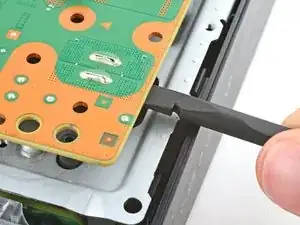
    • Insert the flat end of a spudger between the top shield plate and the main board and pry up to release the plate. Work your way around the perimeter until it separates completely.

  24. CiSpZEdvoj4uRAsR
    CiSpZEdvoj4uRAsR
    WSOOBgt5lxPAutr5
    • Lift and remove the top shield plate.

    • During reassembly, this is a good point to replace any thermal pads on the top of the main board, if necessary. The pads may be stuck to both the top shield plate and the main board.

    • It's important that the replacement pads are the same thickness as the originals, otherwise the foam around the APU may not seal properly.

  25. sJLuyaIAkQmGJKrW
    sJLuyaIAkQmGJKrW
    MTahVcT5YnoTAgng
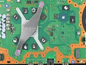
    • Use a T8 Torx Security screwdriver to remove the four remaining screws securing the main board:

    • Two 7.5 mm‑long main board screws

    • Two 16.3 mm‑long screws securing the APU tension bracket

    • Don't remove or install one screw at a time, or you may damage the APU. During disassembly and reassembly, alternate between the two screws a 1/2 turn at a time to maintain even pressure on the bracket.

  26. ANqBiLBTDxbLiAwP
    ANqBiLBTDxbLiAwP
    D5YvO1ReZJZbJGJx
    JpnAUEOIpSuZySlV
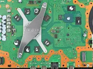
    • Lift and remove both APU brackets from the board.

    • During reassembly:

    • Put the bracket with plastic arms on first so the pegs go into their cutouts.

    • Then, put the metal bracket onto the plastic one so they're perpendicular and the screw holes line up.

  27. MaABQIsEHVNVnJdS
    MaABQIsEHVNVnJdS
    ng2LDHKf3UpZeXAC
    5FRSaGCFE3XkAEgk
    • Don't try to fully remove the motherboard during this step—the corner near the power button is still secured by metal prongs, which will be disconnected in the next step.

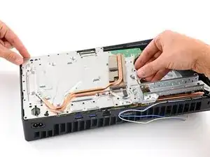
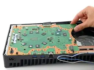
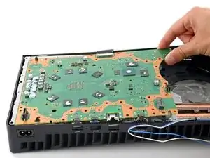
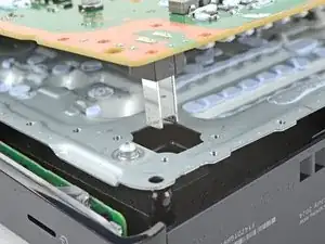
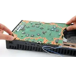
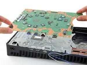
    • Gently lift the edge of the motherboard with the large cutout to partially separate it from the bottom shield plate.

    • With the board lifted, insert the flat end of a spudger between the board and the bottom shield plate and gently twist to separate them. Work your way around the perimeter of the board.

    • Many small thermal pads bond the main board to the metal shield plate underneath. Depending on the age of your PlayStation and the condition of the pads, it may take significant force to separate the board.

  28. Mhy16f4gKOcRcdRf
    Mhy16f4gKOcRcdRf
    oq4wFddiZHZV3l3j
    vaOCQyFaBtE6hFu2
    • The power supply is connected to the bottom of the main board assembly by metal prongs that plug into the bottom left corner.

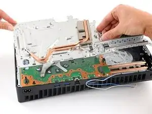
    • Insert the flat end of a spudger between the board and the lower shield plate, by the two parallel solder joints near the corner with the power button.

    • Use your spudger to pry up the board until the two prongs come completely out of their socket.

    • You should feel the prongs slide out.

    • During reassembly, press down on the corner of the board to fully seat the prongs in the power supply—you should feel them slide into place.

  29. U2fVCjHiXlWA3Fet
    U2fVCjHiXlWA3Fet
    4VDybHPHBemwPGtN
    • Remove the main board, flip it over, and carefully lay it on a clean work surface, so the APU is facing up.

    • Don't press the board against your work surface, or you may damage fragile components.

    • During reassembly:

    • Make sure all cables that connect to the board are out of the way so they don't get trapped underneath.

    • Carefully flip the board over so the APU is on the bottom, making sure no liquid metal spills.

    • Keep the board level and lower it into place.

  30. GASsJn2DpEacuTws
    GASsJn2DpEacuTws
    fAybSBdEUDZXOVNw
    LcNcbBL1eYYrHZDS
    • Wear gloves to protect your skin from the liquid metal.

    • If you have a disposable syringe, you can use it to suck up any large pools of liquid metal. Don't use the syringe containing your new liquid metal.

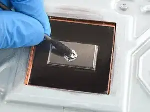
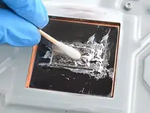
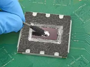
    • Starting with the heatsink: apply a few drops of highly-concentrated (greater than 90%) isopropyl alcohol to a cotton swab and carefully clean up all of the liquid metal from the heatsink surface.

    • Removing the liquid metal can be tricky—it spreads and smears easily. Switch to new cotton swabs and apply more alcohol as necessary.

    • Use the same cleaning process to thoroughly clean up all of the liquid metal residue.

    • The surface needs to be completely clean for the new liquid metal to work properly.

    • Let the heatsink dry completely.

  31. DF6EgLFKGGfLpfph
    DF6EgLFKGGfLpfph
    YYPkoDStZKQXVBsA
    • Don't remove the foam barrier that surrounds the APU.

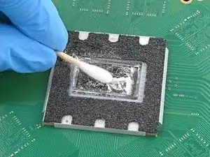
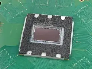
    • Just as you did for the heatsink, clean and remove all of the old liquid metal and its residue from the APU.

    • Don't let any of the liquid metal drip onto the board. Liquid metal is conductive and could cause a short. The foam barrier keeps the liquid metal from leaking out.

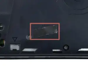
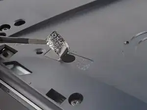
    • This is a good point to replace any thermal pads on the bottom of the main board, if necessary. The pads might be stuck to both the bottom shield plate and the main board.

    • Make sure your replacement pads are the same thickness as the originals, or the foam around the APU may not seal properly.

  32. URGOSsldQKLHiq3q
    URGOSsldQKLHiq3q
    5brRTbf3WEJkjJRM
    OOVgGhGDR4krn4Er
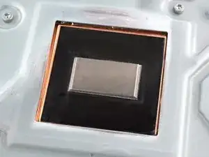
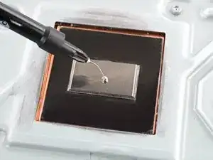
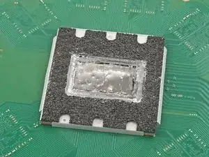
    • Apply a small drop of liquid metal to the heatsink (not the APU)—about the size of a small matchstick head.

    • If your liquid metal syringe has multiple applicator heads, use the one with a small, needle-like tip.

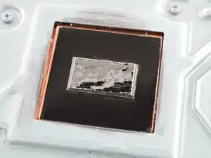
    • Use the spreader that came with your liquid metal or a new cotton swab to lightly push down on and evenly spread the liquid metal across the entire surface.

    • If there's excess liquid metal anywhere, use the syringe to suck it back up.

  33. wyGgSNc5ph3xIkdY
    wyGgSNc5ph3xIkdY
    uRBAebpaSvCDXAjC
    • Your cotton swab from the previous step should still have some liquid metal left on it.

    • Use the same cotton swab to spread a thin layer of liquid metal evenly onto the APU. If you need more liquid metal, lightly dab the cotton swab on the heatsink to transfer some, or apply a very small drop from the syringe.

    • The main board is now ready for reassembly.

Conclusion

To reassemble your device, follow these instructions in reverse order, starting with this step.

Take your e-waste to an R2 or e-Stewards certified recycler.

Repair didn’t go as planned? Try some basic troubleshooting, or ask our Answers community for help.

Spencer Day

Member since: 14/09/22

95592 Reputation

0 comments